
Control system of a technical installation

a technology of control system and installation, which is applied in the direction of electric controller, program control, instruments, etc., can solve problems such as error-proneness, and achieve the effect of cost-effectiveness

Inactive Publication Date: 2014-09-09
SIEMENS AG
View PDF15 Cites 1 Cited by
  • Summary
  • Abstract
  • Description
  • Claims
  • Application Information

AI Technical Summary

Benefits of technology

The invention aims to improve control systems by overcoming disadvantages and making them more cost-effective. The solution involves a redundant embodiment and a software layer that can be used repeatedly. The basis of the invention is to enable quicker and cost-effective coupling of communication channels to field devices and the target system. The connecting channel is embodied as redundant to increase reliability, and standardized values are alternately exchanged to reduce processing costs.

Problems solved by technology

The majority of protocols of field devices nevertheless do not support a redundant coupling so that a unique communication link has to be configured for the coupling in each instance.
Configuring this selection logic for each individual case is associated with a high outlay and is also error prone.

Method used


Image

  • Control system of a technical installation
  • Control system of a technical installation

Examples


Embodiment Construction

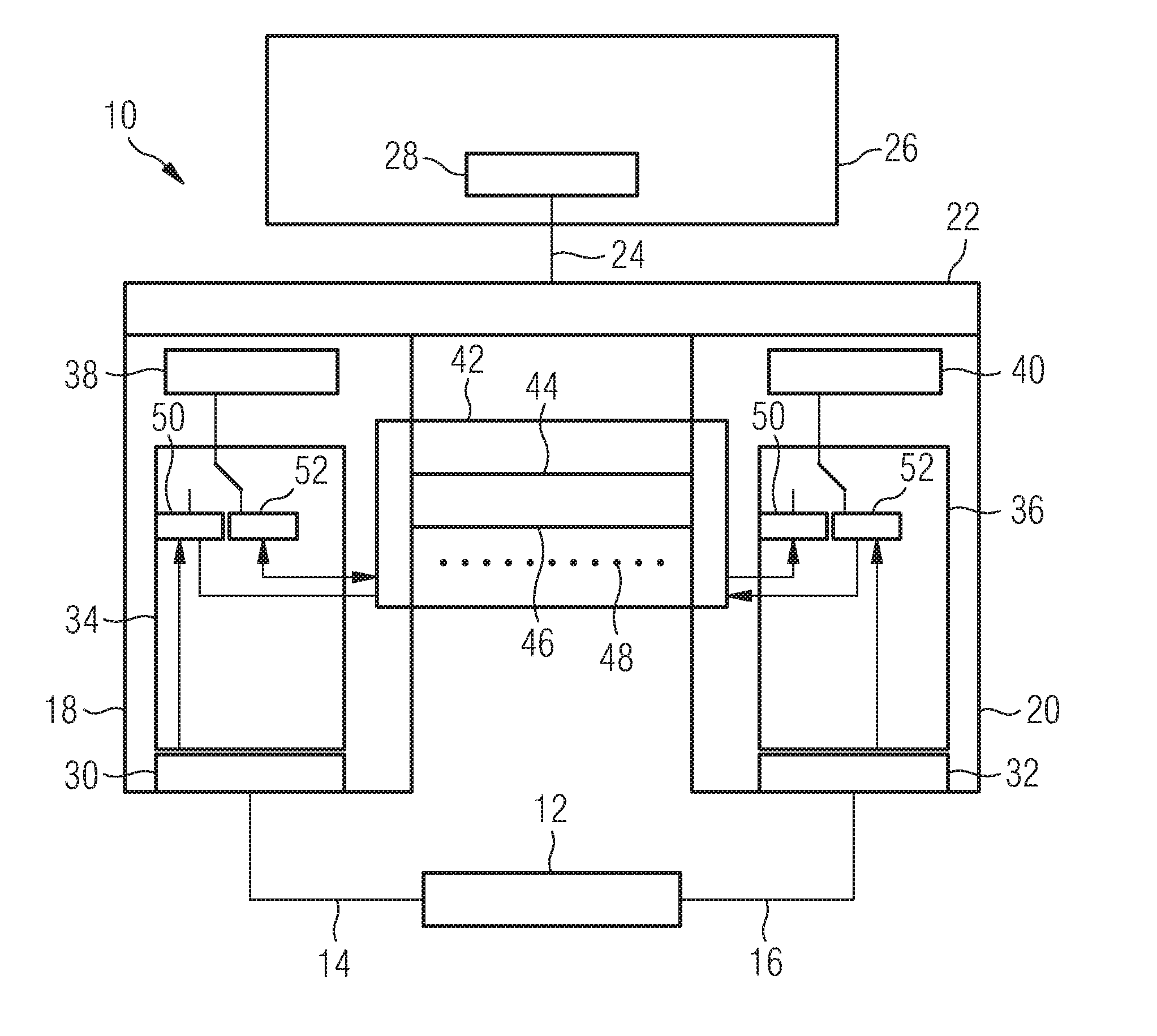
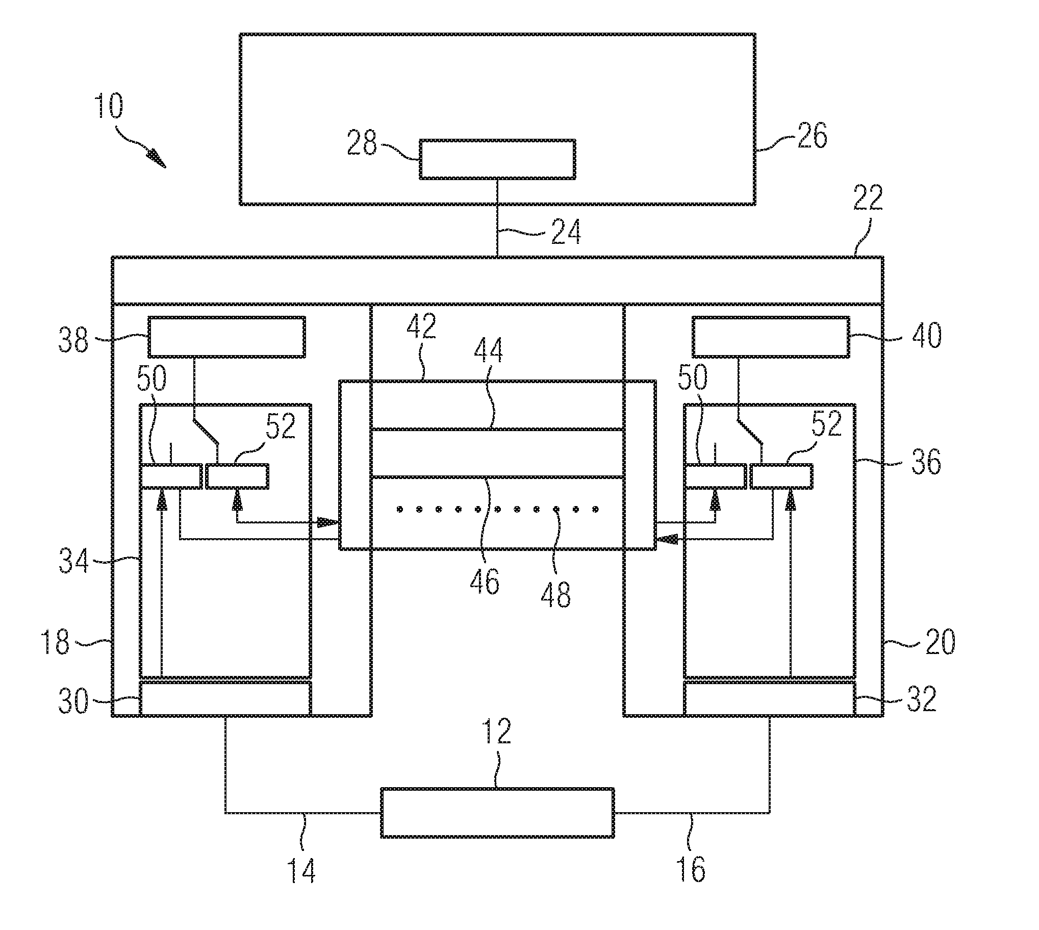
[0020]FIG. 1 shows a control system 10, to which field device 12 is connected. The field device 12 is for instance a turbine or a generator of a power plant. The field device 12 is connected to a first communication channel 18 and / or a second communication channel 20 by means of a first line 14 and a second line 16. The communication channels 18 and 20 are embodied in the form of a computer module and are provided so as to control individual protocol values of a protocol provided redundantly by the field device 12 in respect of its exactitude in each instance.

[0021]The protocol values considered to be exact are transmitted by the communication channels 18 and 20 to a masking logic 22, which conveys these via a line 24 to a target system 26. The target system 26 is a configuration interface for the protocol values for instance.

[0022]Each individual communication channel 18 and 20 includes a driver logic 30 and / or 32, by means of which the values provided by the field device 12 are co...


PUM


Abstract

A control system of a technical installation including at least one field device which makes available at least two redundant protocol values that are converted by the control system into a single non-redundant functional value is provided. The control system is provided with at least two redundant communication channels for converting the at least two redundant protocol values, the channels controlling the respective protocol value with respect to its exactitude and transmitting an exact protocol value.

Description

CROSS REFERENCE TO RELATED APPLICATIONS[0001]This application is the US National Stage of International Application No. PCT / EP2008 / 051820 filed Feb. 14, 2008 and claims the benefit thereof. The International Application claims the benefits of German Patent Application No. 10 2007 007 537.7 DE filed Feb. 15, 2007; both of the applications are incorporated by reference herein in their entirety.FIELD OF INVENTION[0002]The invention relates to a control system of a technical installation comprising at least one field device which makes available at least two redundant protocol values that are converted by the control system into a single non-redundant functional value.BACKGROUND OF INVENTION[0003]With control systems of technical installations, like for instance power plants, turbines or generic engines, it is in many cases necessary, due to operational reliability, to redundantly couple the protocols made available by the respective field devices. The majority of protocols of field dev...

Claims


Application Information

Patent Timeline
Patent Type & Authority Patents(United States)
IPC IPC(8): G05B9/02G05B9/03G05B19/042
CPCG05B9/03G05B19/0428G05B2219/25153G05B2219/25157G05B2219/24196G05B2219/24173
Inventor GERSTMAIER, ALEXEJSCHLARB, EBERHARDSTEINHAUER, GUIDO
Owner SIEMENS AG
Learn More