Coolant bridging line for a gas turbine, which coolant bridging line can be inserted into a hollow, cooled turbine blade

Inactive Publication Date: 2015-04-23
SIEMENS AG
View PDF1 Cites 2 Cited by
  • Summary
  • Abstract
  • Description
  • Claims
  • Application Information

AI Technical Summary

Benefits of technology

[0017]The advantages associated with embodiments of the invention include in particular in the fact that, by virtue of the modification to the coolant bridging lines with respect to their thermal and fluidic properties, a flexible adaptation to temperature distributions within a gas turbine, which arise during operati

Problems solved by technology

In this context, it has surprisingly been found that the coolant bridging lines used have hitherto in no way been used to improve service life while maintaining a constant efficiency.
However, it

Method used


Image

  • Coolant bridging line for a gas turbine, which coolant bridging line can be inserted into a hollow, cooled turbine blade
  • Coolant bridging line for a gas turbine, which coolant bridging line can be inserted into a hollow, cooled turbine blade
  • Coolant bridging line for a gas turbine, which coolant bridging line can be inserted into a hollow, cooled turbine blade

Examples


Embodiment Construction

[0024]Identical parts are provided with the same reference signs in all figures.

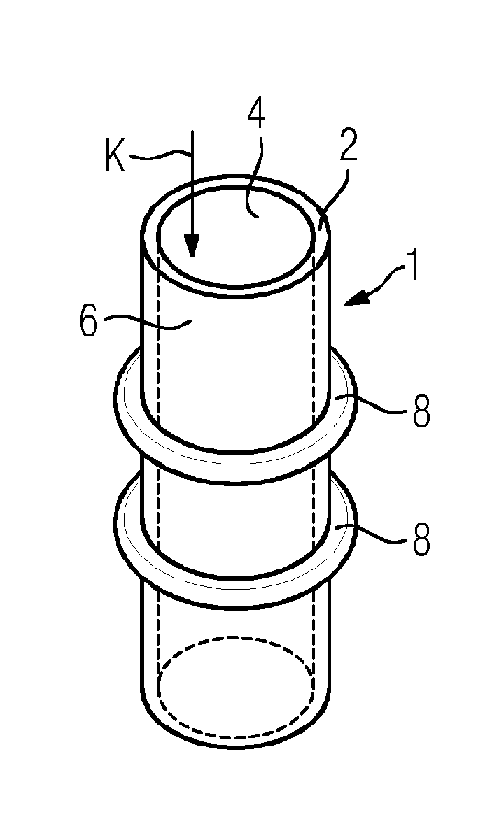
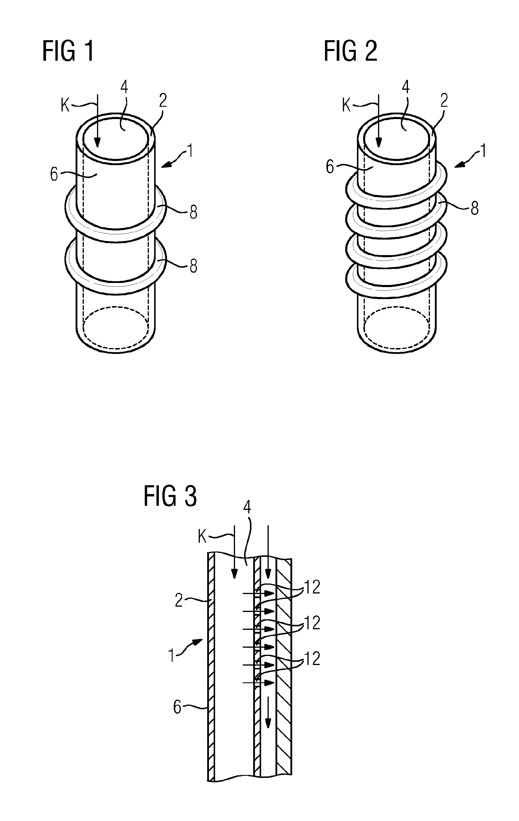
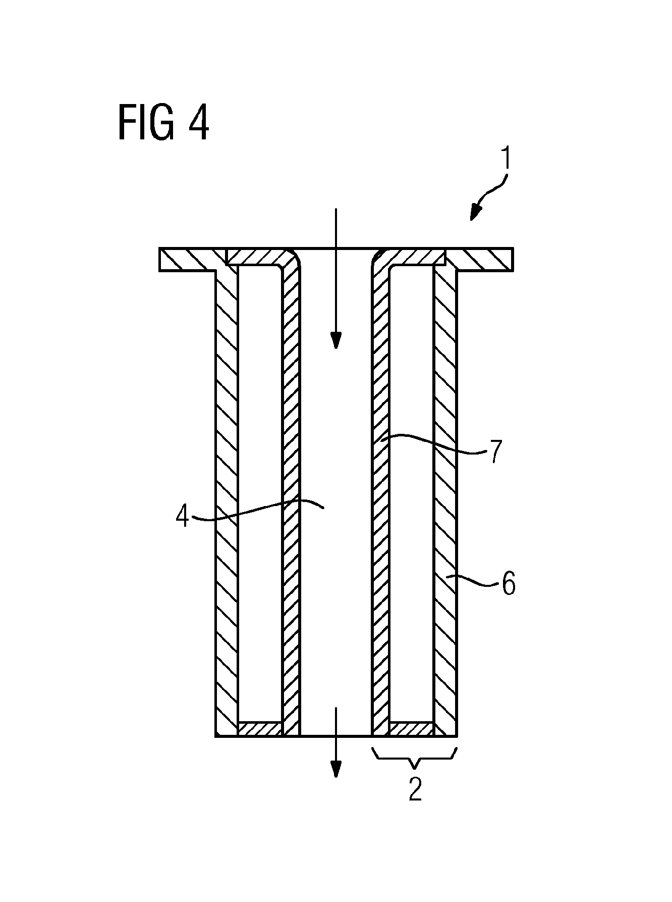
[0025]FIG. 1 shows a cylindrical coolant bridging line 1. This is inserted into a hollow, cooled turbine guide blade (not shown) and extends between the blade roots of the turbine guide blade. The coolant bridging line 1 has a wall 2 which separates the inner side 4 and the outer side 6 of the coolant bridging line 1. Coolant K, in the exemplary embodiment air, is conveyed inside the coolant bridging line 1.

[0026]Annular turbulators 8 are arranged on the outer side 6. In the alternative exemplary embodiment according to FIG. 2, however, the turbulators 8 are arranged in a helical manner. Equally, turbulators not shown in more detail can be arranged on the inner side of the coolant bridging line 1. In addition, the coolant bridging lines according to FIGS. 1 and 2 are provided with a ceramic coating.

[0027]FIG. 3 shows a coolant bridging line 1 together with the adjacent end side 10 of the guide blade into...


PUM

PropertyMeasurementUnit
Pressureaaaaaaaaaa
Heataaaaaaaaaa
Thermal conductivityaaaaaaaaaa

Abstract

A coolant bridging line for a gas turbine having inner and outer sides which are separated by a wall, wherein the coolant bridging line extends from a first component of the gas turbine to a second component of the gas turbine is provided herein. The coolant bridging line for a gas turbine provides a further increase in the service life of the components of the gas turbine possible with a degree of efficiency which is nevertheless as high as possible. To this end, the coolant bridging line has means which change the heat transfer between and/or the flow conditions on the inner and outer sides.

Description

CROSS REFERENCE TO RELATED APPLICATIONS[0001]This application is the US National Stage of International Application No. PCT / EP2013 / 059859 filed May 14, 2013, and claims the benefit thereof. The International Application claims the benefit of German Application No. DE 102012209549.7 filed Jun. 6, 2012. All of the applications are incorporated by reference herein in their entirety.FIELD OF INVENTION[0002]The invention relates to a coolant bridging line for a gas turbine, which coolant bridging line can be inserted into a hollow, cooled turbine blade and has inner and outer sides separated by a wall, wherein the coolant bridging line extends from a first component of the gas turbine to a second component of the gas turbine.BACKGROUND OF INVENTION[0003]A gas turbine is a turbomachine in which a gas under pressure expands. It includes a turbine or expander, a compressor connected upstream thereof, and a combustor connected between the two. All of the blades of the compressor and of the t...

Claims


Application Information

Patent Timeline
IPC IPC(8): F01D5/14F01D9/02F01D5/18
CPCF01D5/147F01D5/187F05D2300/20F05D2260/2212F05D2260/201F01D9/02F01D5/189F01D9/065F05D2260/231Y02T50/60F01D5/18
Inventor AHMAD, FATHI
Owner SIEMENS AG
Why Eureka
Try Eureka