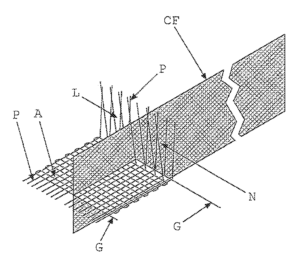
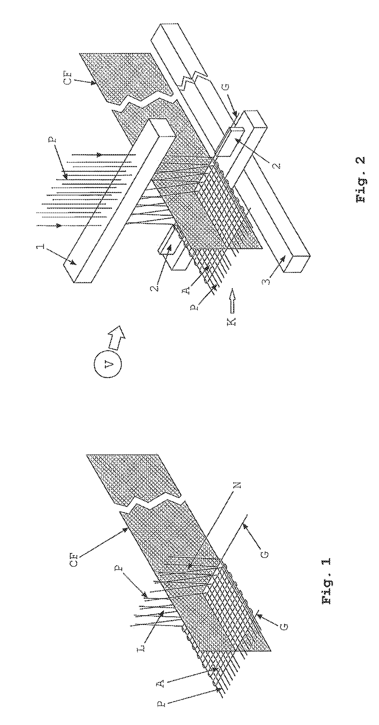
In other words, it has not been possible to manufacture a profiled beam-like 3D fabric item wherein its web has, for example a braided structure, and the
flange has, for example a woven structure, and the web and
flange are interconnected to each other mutually in their thickness directions, i.e. the planes of web and flange intersect each other at their junction.
Likewise, it has not been possible to manufacture a profiled beam-like 3D fabric item with its web having a woven structure, the flange having a braided structure, and the web-flange being interconnected to each other by their respective constituent yarns which mutually pass through the thickness directions of each other.
A
textile preform with no / poor
structural integrity collapses easily making its handling and impregnation with matrix difficult, besides causing
fiber misalignments, improper
fiber distributions,
fiber breakages etc., which contribute to impair performance.
There does not appear to be any method available presently for practically, effectively and economically producing a 3D fabric item with the aforementioned characteristic fabric architectural or structural constructions.
These existing methods do not provide possibilities to produce 3D fabric items that have completely different structural architectures of the web / s and flange / s.
Further, these methods do not provide either a web or a flange or both web and flange comprising a combination of different fabric architectures.
Also, they are limited in terms of their ability to produce only either a specific or few varieties of forms / shapes and dimensions.
As a consequence, these existing methods do not provide much scope in
engineering complex 3D fabric items which require broad and deep performance and
functional features.
That these methods are ineffective is evidenced by the fact that they continue to remain industrially unsatisfactory and unattractive.
However, there is no mutual through-thickness connection of the web and flange.
The direct or special 3D fabric-
forming processes provide through-thickness connection of web and flange, but do not produce a structurally integrated web (or flange), and both the web and the flange with relatively different fabric architectures.
Also, as will be noticed they are practically complicated and inefficient.
Composite materials comprising such 3D fabric items delaminate, i.e. fail by
cracking and splitting.
As a consequence, the stitched / joined materials tend to be unreliable and hence are unusable in high-performance applications.
However, as with the stitched / joined materials, this material also does not create the web and flange which intersect in mutual through-thickness manner.
However, such connecting and bridging of oppositely folded sections fail because of the void / empty ‘triangular’ space that is created at the web-flange junction, whereby the structure is rendered weak, prone to
delamination, and hence unreliable.
Some other disadvantages associated with the stitching method include: (a) mismatch of fibre properties between those used for stitching and that constituting the fabric / s, (b) fibre material used for stitching being incompatible with the matrix used for making
composite material, (c) relatively loose, shaky and weak junctions make the structure unreliable and difficult to
handle and predict performance behavior, (d) lower reliability due to fibre breakages arising from handling and stitching action, (e) fibre displacements and direction misalignments arising from handling and stitching action, (f) being labour intensive and
time consuming, (g) causing fibre
waste generation, which adversely impacts the environment, (h) being expensive without providing real advantages, and (i) unsuitable for creating 3D fabric items with complex shapes.
Furthermore, to enable stitching, the thickness of the web / s and flange / s has to be kept relatively low, which in turn directly renders the obtained profiled material relatively lower in mechanical performance (due to relatively low amount of fibers) and hence unsuitable for heavy-duty applications.
In any case, stitching / joining two fabrics does not overcome the fundamental problem of
delamination arising from absence of a mutual through-thickness connection between web / s and flange / s at their junction / s.
The
direct production methods, exemplified by U.S. Pat. No. 5,021,281, U.S. Pat. No. 5,783,279, U.S. Pat. No. 5,121,530, U.S. Pat. No. 4,779,429, U.S. Pat. No. 4,686,134, U.S. Pat. No. 6,019,138 and WO91 / 06421 also do not provide satisfactory and reliable 3D fabric reinforcements.
As can be noticed, these direct processes are unlike the indirect or stitching processes described earlier in that they do not use any ready or pre-produced suitable fabric / s that are structurally integrated to produce the required 3D fabric items.
These processes cannot create a mutually intersecting junction of structurally integrated web / s and flange / s by using suitable pre-produced fabric / s of given architecture / s and a relatively different fabric architecture that is produced by integrating the yarns used in the process.
Because of lack of any mutual structural
connectivity / integrity between these (C) yarns, the web section remains as two separate sheets and hence unstable and prone to get easily disturbed and damaged.
It is not sufficiently filled with yarns to create a
solid / undivided fabric plane.
As a consequence, a web having a relatively low amount of yarns and without any
structural integrity can neither accord performance nor be resistant to
distortion during handling / further
processing, such as matrix impregnation, and associated consequent damages.
In fact such a limp web will tend to collapse under its own weight, as well as that of the upper flange's weight.
Clearly, this method has extremely limited scope of applicability and usefulness.
Such a structure thus does not provide the necessary
structural stability / rigidity to the flanges.
Apart from the above limitations of the method according to U.S. Pat. No. 5,021,281, another important drawback of it is that it does not produce a profiled beam-like 3D fabric item with its surfaces at the longitudinal edges of either web / s or flange / s or both of these (depending on the profile's cross-section) with a taper to prevent concentration of stresses at the edges.
Similarly, it does not produce a profiled beam-like 3D fabric item with filleted or rounded corners, where the surfaces of the web / s and flange / s meet, to prevent concentration of stresses at the corners.
Also, the foregoing method does not produce a profiled beam-like 3D fabric item wherein the web section has its constituent yarns in 0° / 90° orientations and the flange section has its constituent yarns in + / −θ° bias orientations.
Further, this method does not produce the web / s and / or flange / s of multiple individual / separate but integrated
layers.
Also, this method cannot process any ready or pre-produced fabric in either its web / s or flange / s.
In fact the corresponding associated processes, namely knitting, weaving and braiding are stated therein to degrade the axial strength and stiffness of fibers and thereby unsuitable.
As the pre-form itself has no
structural integrity, the constituent fibers are prone to delamination, disorientation, and loosing fiber distribution and
linearity.
Such a pre-form would naturally easily disintegrate and collapse, for example during
pultrusion process, even before being made into a
composite material.
In any case, this method also cannot process any pre-produced fabric in either its web / s or flange / s.
These yarns constituting the web are themselves not mutually integrated into an intertwined structure, like that of a
braid, and therefore this 3D fabric item is also unstable and cannot support itself.
It will tend to collapse and hence get distorted and damaged easily.
The web producible by this method is again a relatively trellis-like open construction resembling a truss structure whereby lack of sufficient yarns renders it directly lower in performance.
Also, sliding the flanges (101 and 102) over the web yarns (202 and 203) to separate them apart to required distance will naturally cause mutual abrasion of the involved yarns which in turn will cause damage to the involved yarns and hence result again in lower performance.
Such an action will also cause
distortion of the structure and thereby cause corresponding reduction in performance and reliability.
Once again, this method also cannot process any pre-produced or ready fabric in either its web / s or flange / s.
(These production steps do not technically comply with the principle of weaving.)
Although the produced structure is an improvement over the earlier attempts, it still suffers from being a homogeneous structure in both the web / s and flange / s besides having other shortcomings presented earlier.
Yet again, this method also cannot process any ready or pre-produced fabric in either its web / s or flange / s.
Yet again, this method also cannot process any ready or pre-produced fabric in either its web / s or flange / s.
This method also cannot process any ready or pre-produced fabric in either its web / s or flange / s and connect them in their mutual thickness directions.
This method also lacks in creating the other performance requirements stated earlier.
As with various methods discussed above, this method also cannot process any ready or pre-produced fabric in either its web / s or flange / s to produce the stiffened panels.
As can be observed now, another important practical limitation of these known methods is that they cannot produce 3D fabric beams such as profiled beams with relatively large cross-section areas and the
fibre content that are typically needed for most applications.
Further, these discussed methods cannot incorporate yarns / tows in a combination of different orientations in flange / s and web / s of a 3D fabric item.
Further, these methods cannot produce a 3D fabric item, such as an I cross-section beam, wherein the two flanges have + / −θ° bias
angular orientation of yarns and the web has its yarns oriented in longitudinal (90°) and lateral (0°) directions.
Also, they cannot produce a 3D fabric item, such as an I-beam, wherein both the flange / s and the web / s comprise yarns in + / −θ° bias as well as longitudinal (90°) and lateral (0°) directions in required different sequential lay-up arrangements.
Also, they cannot produce a 3D fabric item, such as an I-beam, wherein the yarns in one flange are arranged relatively differently in architecture compared with the arrangement of yarns in the other flange.
Further, none of these known methods, or their combinations, can produce complex 3D fabric items comprising web / s and flange / s such as those having combined curved-straight sections, bends, converging / diverging shapes, circular objects, varying dimensions in one or more directions, relatively inverted cross-sections, sine curved shapes etc.
Clearly, 3D fabric items which are unlike profiled beams, and therefore do not necessarily comprise planar / linear webs and flanges, cannot be produced by these existing processes.
Further, all these known methods are not capable of handling and integrating a ready or previously produced fabric with the yarns used for producing a fabric in the process.
In other words, they cannot produce a 3D fabric item by using a suitable pre-produced fabric of a given architecture and add it on, or combine it, in an integrated manner with the fabric being produced using yarns.
By these known processes it is not possible to obtain integration of a pre-produced add-on fabric with a just-produced interacting
woven fabric in their mutual through-thickness directions to create web / s and flange / s which mutually intersect at their junction's and directly result in a wholly integrated profiled beam-like 3D fabric item.
A person skilled in the art can infer now from the foregoing presentation that the presently available methods are insufficient, inefficient and incapable of producing truly advanced and complex 3D fabric items, for meeting the increasing mechanical performance and reliability demands of emerging high-performance composite materials, practically and in a cost effective manner.


