
Multi-core processor system configured to constrain access rate from memory

a multi-core processor and access rate technology, applied in computing, instruments, data conversion, etc., can solve the problems of inefficient hardware use, interfering with each other's performance, and typically disabled all but one core of the multi-core processor

Active Publication Date: 2015-01-27
ROCKWELL COLLINS INC
View PDF11 Cites 25 Cited by
  • Summary
  • Abstract
  • Description
  • Claims
  • Application Information

AI Technical Summary

Benefits of technology

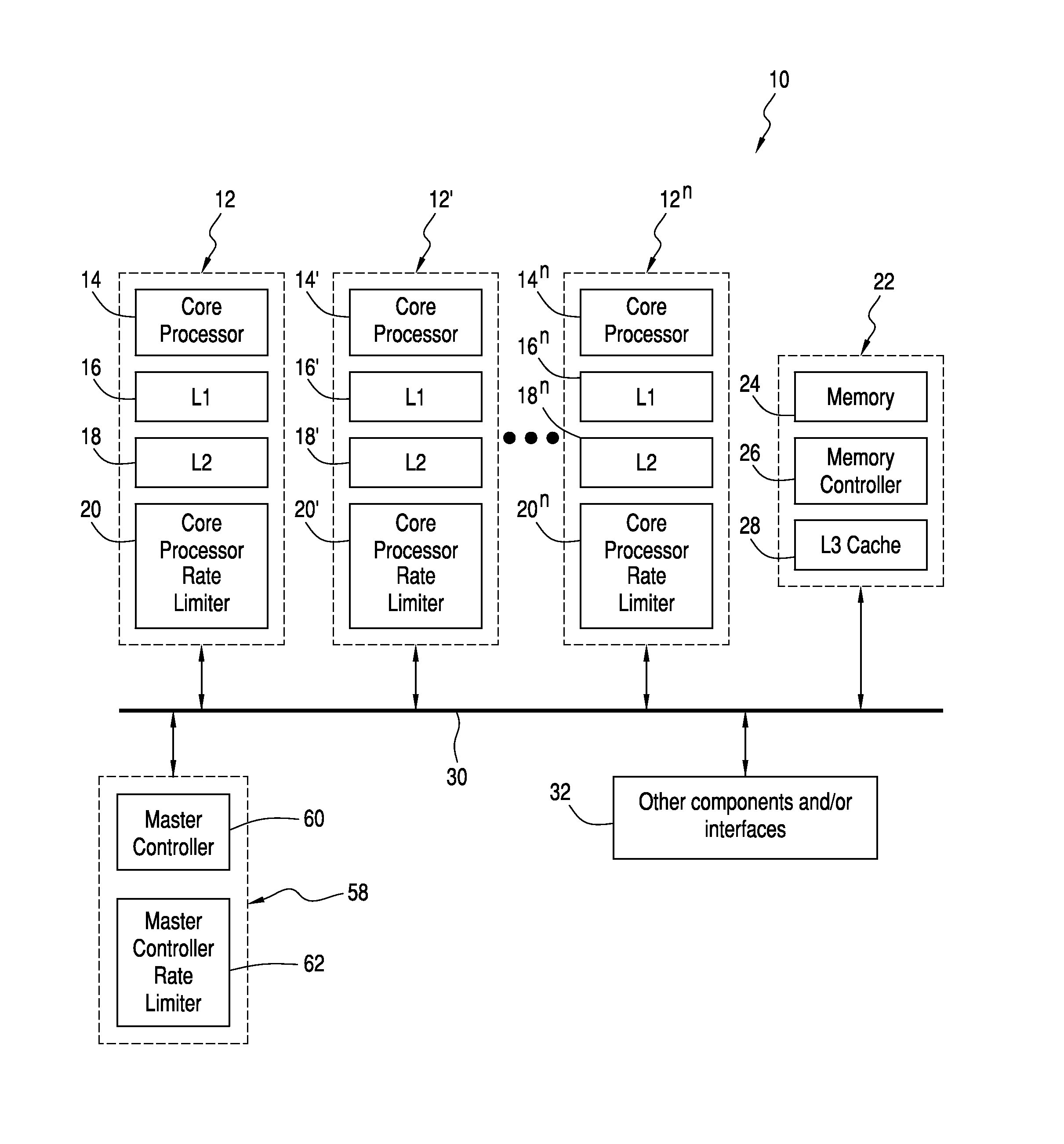
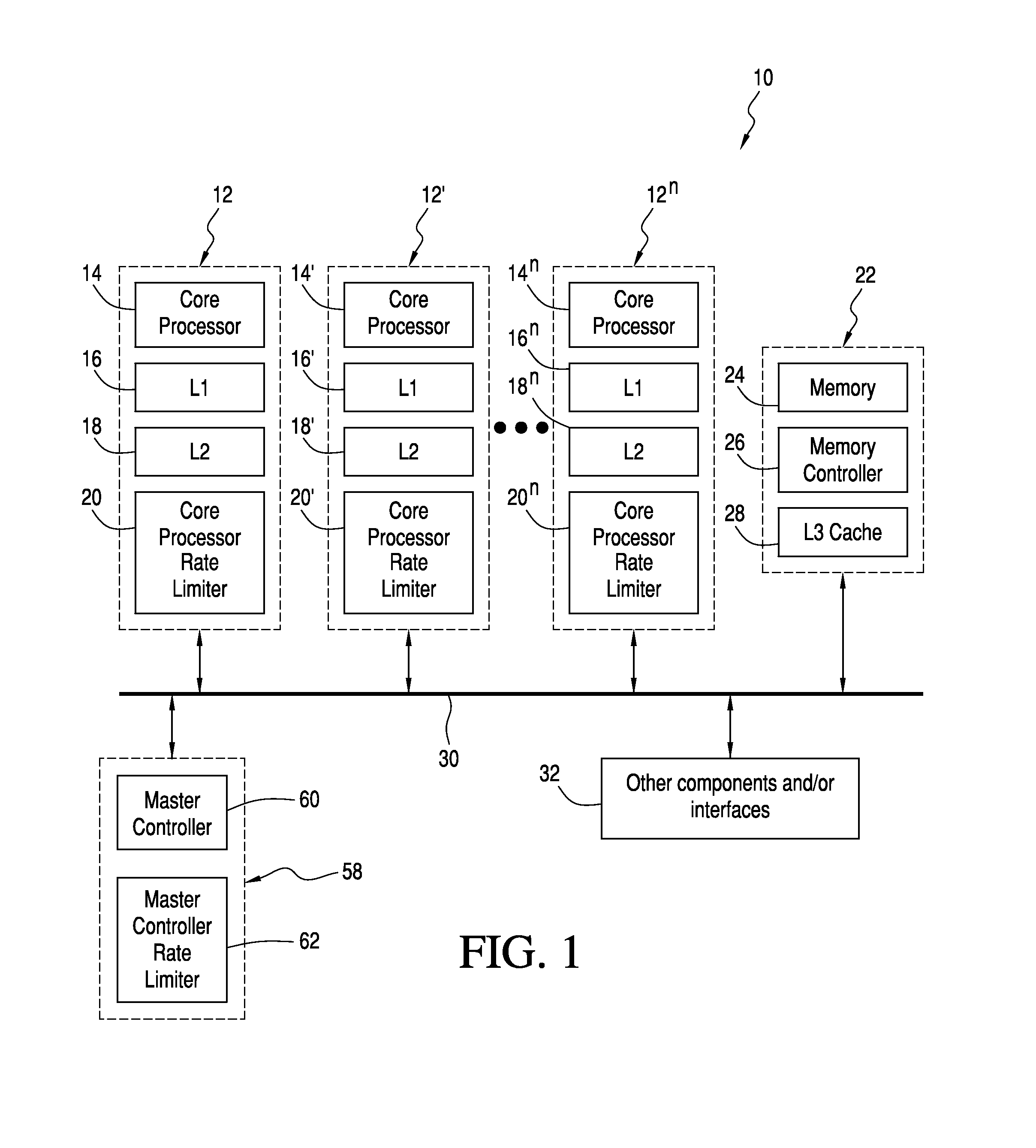
This patent describes a multi-core processor system that includes multiple cores, a memory system, and a common access bus. Each core includes a processor and a cache, and there is a rate limiter to control access to the memory system. The system also includes a master controller system with its own rate limiter. The headaches of analyzing and configuring systems are avoided by isolating the cores for analysis without imposing system-level constraints. The technical effects of this invention include improved performance and efficiency of multi-core processor systems by limiting access to memory and controlling data access rates.

Problems solved by technology

However, the cores and master controllers of a multi-core processor often share hardware resources and can significantly interfere with each other's performance.
As a result, when such multi-core processors are used to implement ARINC 653 systems, all but one of the cores in the multi-core processors is typically disabled.
This is a significantly inefficient use of hardware, and the inefficiency worsens as the number of cores per processor increases.
This is an artificial constraint that generally generates undesired dead times. This also results in the necessity to synchronize the cores in the core processors making the design approach relatively complex.
This constraint, as well as other constraints that exist, mean that the multicore processor will be less efficiently utilized.
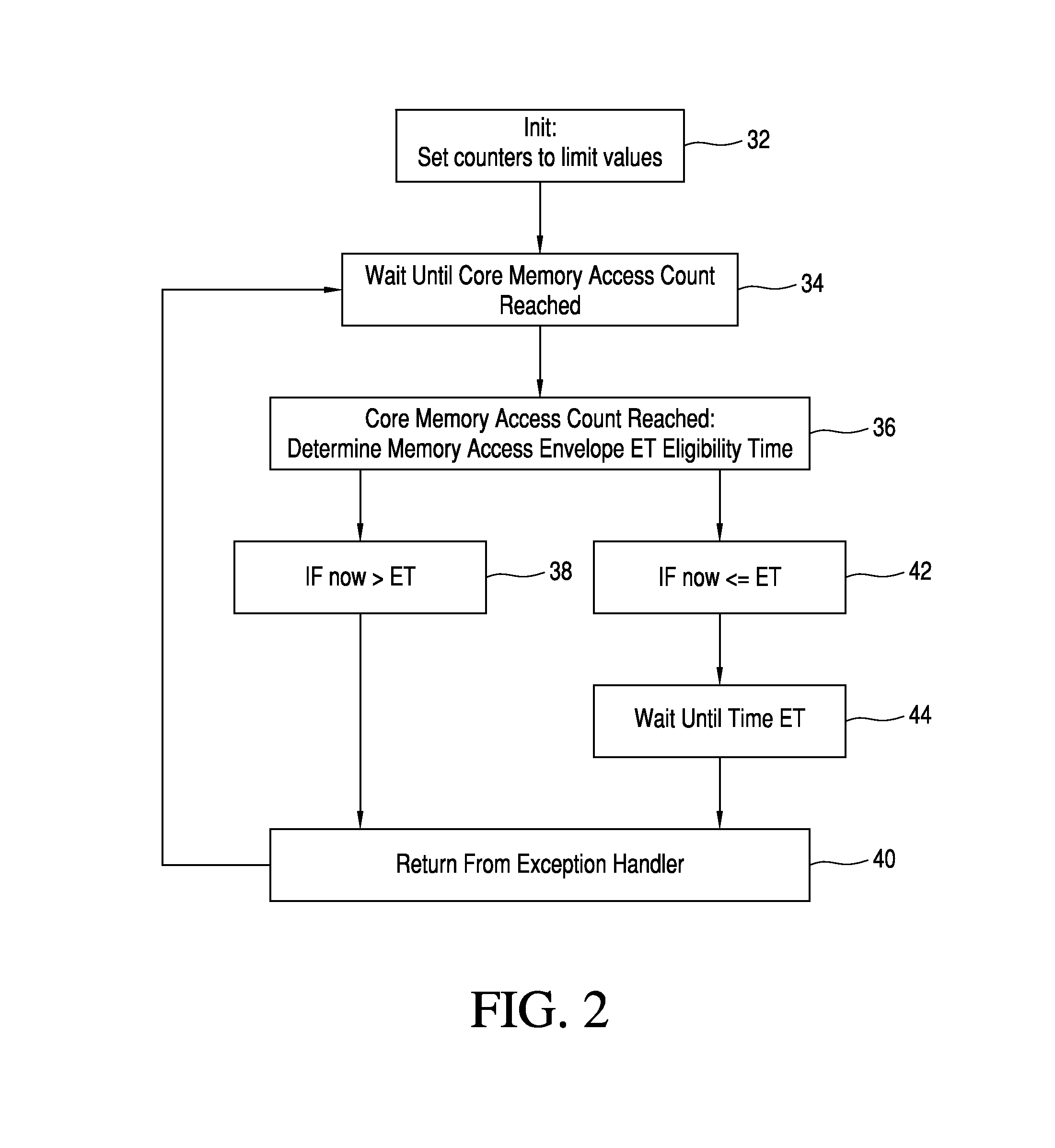
During multicore operation a concern is that a core may make excessive use of DDR memory access relative to the normal behavior.
The result is that the processor capacity is significantly degraded for the other cores.

Method used


Image

  • Multi-core processor system configured to constrain access rate from memory
  • Multi-core processor system configured to constrain access rate from memory
  • Multi-core processor system configured to constrain access rate from memory

Examples


Embodiment Construction

[0019]Referring now to the drawings and the characters of reference marked thereon, FIG. 1 illustrates the multi-core processor system of the present invention, designated generally as 10. The multi-core processor system 10 includes a number of cores 12, 12′, . . . 12n. Each core 12 includes a core processor 14, 14′, . . . 14n. A dedicated core cache 16, 18; 16′, 18′; . . . 16n, 18n is operatively connected to each core processor 14, 14′, . . . 14n. Each dedicated cache 16, 18 typically includes an L1 cache 16 operatively connected to an L2 cache 18. L1 and L2 may include instructions and / or data.

[0020]Each core 12, 12′, . . . 12n includes a core processor rate limiter 20, 20′, . . . 20n operatively connected to the dedicated core cache 16, 18; 16′, 18′; . . . 16n, 18n. Each core processor rate limiter 20 is self-constrained to a defined traffic constraint envelope having a burst and rate component. Each traffic constraint envelope is preferably n-way, non-decreasing, and concave. T...


PUM


Abstract

A multi-core processor system includes a number of cores, a memory system, and a common access bus. Each core includes a core processor; a dedicated core cache operatively connected to the core processor; and, a core processor rate limiter operatively connected to the dedicated core cache. The memory system includes physical memory; a memory controller connected to the physical memory; and, a dedicated memory cache connected to the memory controller. The common access bus interconnects the cores and the memory system. The core processor rate limiters are configured to constrain the rate at which data is accessed by each respective core processor from the memory system so that each core processor memory access is capable of being limited to an expected value.

Description

BACKGROUND OF THE INVENTION[0001]1. Field of the Invention[0002]The present invention relates generally to multi-core processor systems and more particularly to multi-core processor systems for avionics systems.[0003]2. Description of the Related Art[0004]In modern avionics systems (for example, in Integrated Modular Avionics (IMA) systems), partitioning operating systems are typically used to meet stringent safety- and mission-critical requirements. Aeronautical Radio Inc. (ARINC) has promulgated the “ARINC Specification 653: Avionics Application Standard Software Interface” family of specifications (generally referred to here as “ARINC 653”).[0005]ARINC 653 defines an APplication EXecutive (APEX) for space and time partitioning for enabling multiple partitions to share a single processor and memory in order to guarantee that applications executing within one partition cannot adversely affect other partitions. Each partition in such an ARINC 653 system represents a separate applica...

Claims


Application Information

Patent Timeline
IPC IPC(8): G06F13/00G06F13/28G06F5/06
CPCG06F5/06G06F13/1652
Inventor MILLER, DAVID A.MATTHEWS, DAVID C.
Owner ROCKWELL COLLINS INC
Learn More