
Multi-mode combined vehicle detection apparatus

A vehicle detection and vehicle technology, which is applied in the field of image information sources, can solve the problems of inability to realize image acquisition and recognition, complicated wiring of application solutions, and reduced recognition efficiency, so as to reduce the number of devices, optimize solutions, and improve reliability. Effect

Inactive Publication Date: 2015-11-25
GUANGZHOU TECTRON INTELLIGENT SCI & TECH CO LTD
View PDF6 Cites 5 Cited by
  • Summary
  • Abstract
  • Description
  • Claims
  • Application Information

AI Technical Summary

Problems solved by technology

[0002] At present, there are many devices on the market that can independently detect the status of parking spaces in parking lots. Although it can detect the status of parking spaces, it is difficult to quickly and accurately obtain vehicle parking status and obtain characteristic information such as license plates due to the limitations of cost and technical means. , or the single cost is too high or the wiring of the application solution is complicated
[0003] Similar products based on full image recognition technology have complicated integrated wiring, and the recognition speed has certain requirements on the lighting and background of the vehicle. When the light is dark or too strong, the recognition efficiency will drop. Although there are technical methods to correct and compensate, the actual application effect Still have certain requirements for light
Products based entirely on ultrasonic detection can quickly and accurately detect vehicle status, but cannot achieve image acquisition and recognition of simple wiring conditions

Method used


Image

  • Multi-mode combined vehicle detection apparatus
  • Multi-mode combined vehicle detection apparatus

Examples


Embodiment Construction

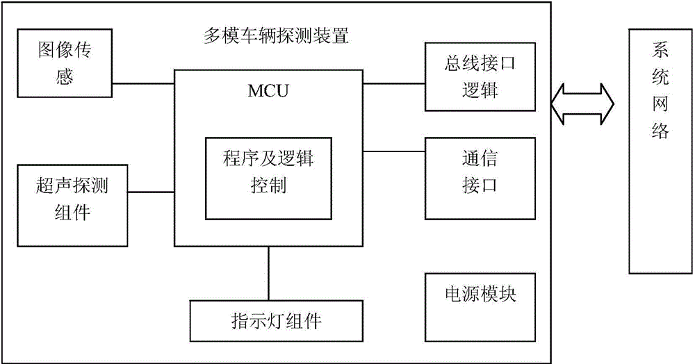
[0017] Such as figure 1 As shown, a multi-mode vehicle detection device mainly includes MCU and logic control, image sensing components, Ultrasonic detection components , communication components ,instruct lamp drive components and power module Wait .

[0018] MCU is the hardware core required for processing and control;

[0019] The image sensing component is composed of one or more image acquisition units, each image unit is responsible for converting the physical quantity of the image into an electrical signal, and is connected to the capture and acquisition unit through the bus interface;

[0020] The ultrasonic detection component detects the occupancy state of the specified area by using the reflection of ultrasonic waves.

[0021] Communication components include communication interface and protocol stack, communication scheduling tasks and other software modules;

[0022] The indicator light component is a circuit of multiple indicator lights controlled by ...


PUM


Abstract

The invention relates to a vehicle state and information identification extracting apparatus. The apparatus detects the parking state of vehicles in a detected area and displays the parking state through an indicating lamp, image information is sent to an access bus according to an instruction of a host computer, and a control instruction of the host computer can be received to enable state information to be displayed. The apparatus comprises an MCU, an image sensing assembly, an ultrasonic detection assembly, a logic control module, a communication assembly, an indicating lamp assembly, a power supply module, etc. Ultrasonic reflection is adopted to detect whether vehicles exit in the detected area, a result is displayed by the indicating lamp and also sent as feedback to the host computer through a communication port, and when the host computer orders the apparatus to send image signals to a bus on the basis of task scheduling situations, the MCU enables signals of the image sensing assembly to be accessed to the bus through the logic control module, and the bus is released if a command of the host computer is cancelled. In this way, a parking lot guiding and vehicle tracking comprehensive system can be easily formed. The mode of the apparatus is formed by an ultrasonic mode and an image mode both of which are effective simultaneously, and the bus control is employed, so the comprehensive cost and the reliability are both guaranteed.

Description

technical field [0001] The invention relates to a parking space detector and an image information source of a license plate recognition device, in particular to a device for quickly determining the parking state of a vehicle through ultrasonic detection and outputting image information using a bus mode. Background technique [0002] At present, there are many devices on the market that can independently detect the status of parking spaces in parking lots. Although it can detect the status of parking spaces, it is difficult to quickly and accurately obtain vehicle parking status and obtain characteristic information such as license plates due to the limitations of cost and technical means. , or the single cost is too high or the wiring of the application solution is complicated. [0003] Similar products based on full image recognition technology have complicated integrated wiring, and the recognition speed has certain requirements on the lighting and background of the vehicl...

Claims


Application Information

Patent Timeline
Patent Type & Authority Applications(China)
IPC IPC(8): G08G1/14
Inventor 祝庆
Owner GUANGZHOU TECTRON INTELLIGENT SCI & TECH CO LTD
Learn More