Transmission method, radio base station and mobile station

a technology of radio base station and transmission method, applied in the direction of network topologies, synchronisation arrangements, wireless commuication services, etc., can solve the problems of requiring a considerable time and taking a long time to determine the desired cell

Inactive Publication Date: 2015-02-03
FUJITSU LTD
View PDF26 Cites 14 Cited by
  • Summary
  • Abstract
  • Description
  • Claims
  • Application Information

AI Technical Summary

Benefits of technology

[0003]At present, mobile communication systems such as cellular telephone systems and wireless LANs (Local Area Network) are widely deployed. Mostly, cellular-type mobile communication systems are employed. In a cellular type, which is one of the communication forms, a plurality of base stations that serve a set of cells forming a service area are installed, and communications are controlled by these base stations cooperating with each other. A mobile station accesses a cell with good communication quality out of cells that are accessible from where it is now, and performs radio communication.
[0013]According to one aspect of the invention, provided is a transmission method of transmitting a synchronization channel in a radio communication system where a plurality of second cells with a smaller radius than a first cell are provided in a service area covered by the first cell where a first synchronization channel is transmitted in a given partial band of a first transmission band, and each of the plurality of second cells is allocated a second transmission band that at least partly overlaps with the first transmission band of the first cell. In this transmission method, in each second cell, a second synchronization channel is transmitted in a partial band of the second transmission band, in which the partial band is different from the given partial band and is different depending on a group of the second cell.
[0013]According to one aspect of the invention, provided is a transmission method of transmitting a synchronization channel in a radio communication system where a plurality of second cells with a smaller radius than a first cell are provided in a service area covered by the first cell where a first synchronization channel is transmitted in a given partial band of a first transmission band, and each of the plurality of second cells is allocated a second transmission band that at least partly overlaps with the first transmission band of the first cell. In this transmission method, in each second cell, a second synchronization channel is transmitted in a partial band of the second transmission band, in which the partial band is different from the given partial band and is different depending on a group of the second cell.
[0013]According to one aspect of the invention, provided is a transmission method of transmitting a synchronization channel in a radio communication system where a plurality of second cells with a smaller radius than a first cell are provided in a service area covered by the first cell where a first synchronization channel is transmitted in a given partial band of a first transmission band, and each of the plurality of second cells is allocated a second transmission band that at least partly overlaps with the first transmission band of the first cell. In this transmission method, in each second cell, a second synchronization channel is transmitted in a partial band of the second transmission band, in which the partial band is different from the given partial band and is different depending on a group of the second cell.

Problems solved by technology

Therefore, it also takes a time.
In short, it requires a considerable time to determine a desired cell in an environment where the large cell and the plurality of small cells coexist.

Method used


Image

  • Transmission method, radio base station and mobile station
  • Transmission method, radio base station and mobile station
  • Transmission method, radio base station and mobile station

Examples


Embodiment Construction

)

[0027]Hereinafter, an embodiment of the present invention will be described in detail with reference to the accompanying drawings. The description begins with an overview of an embodiment to be discussed herein and then proceeds to the details of those embodiments.

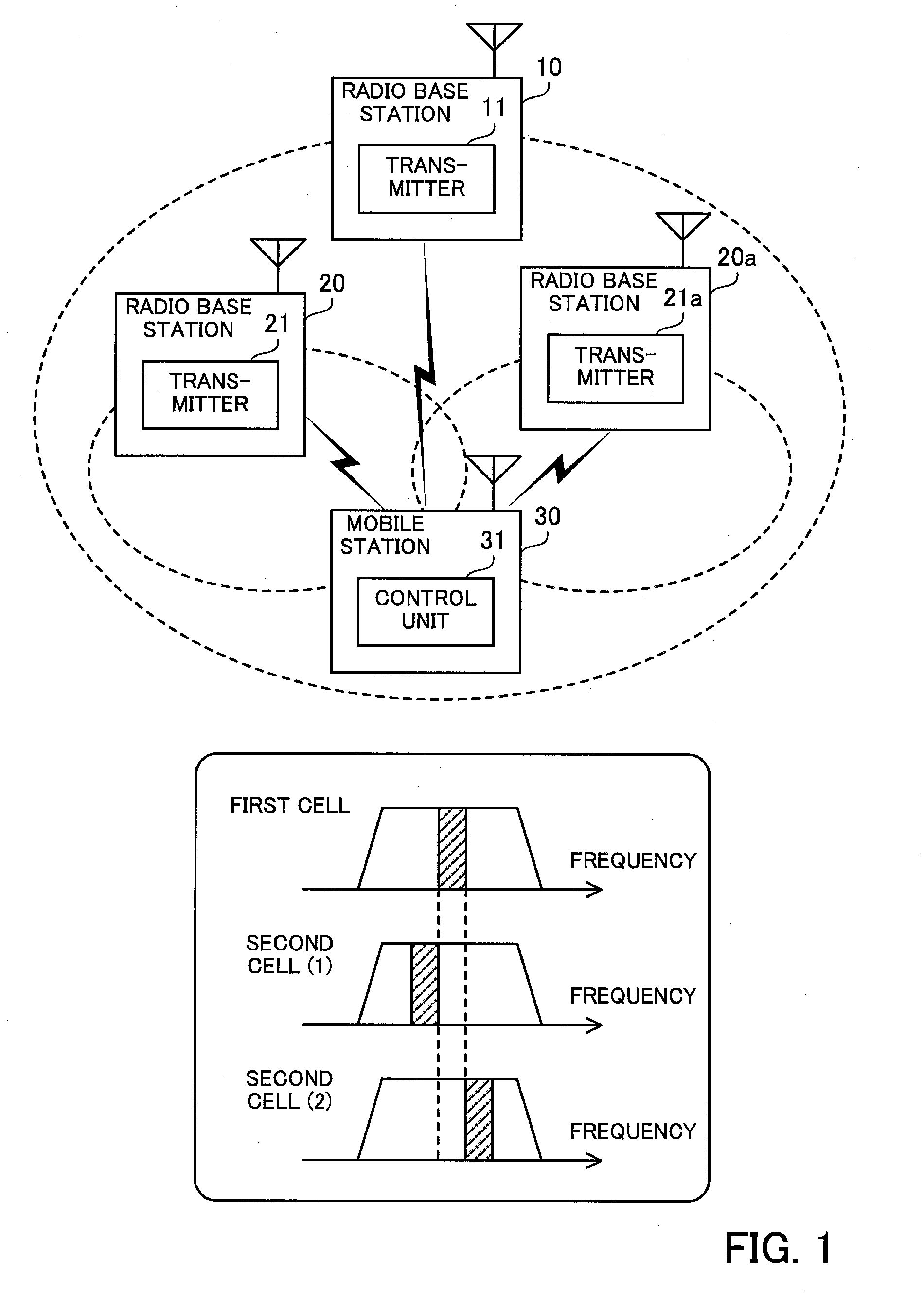
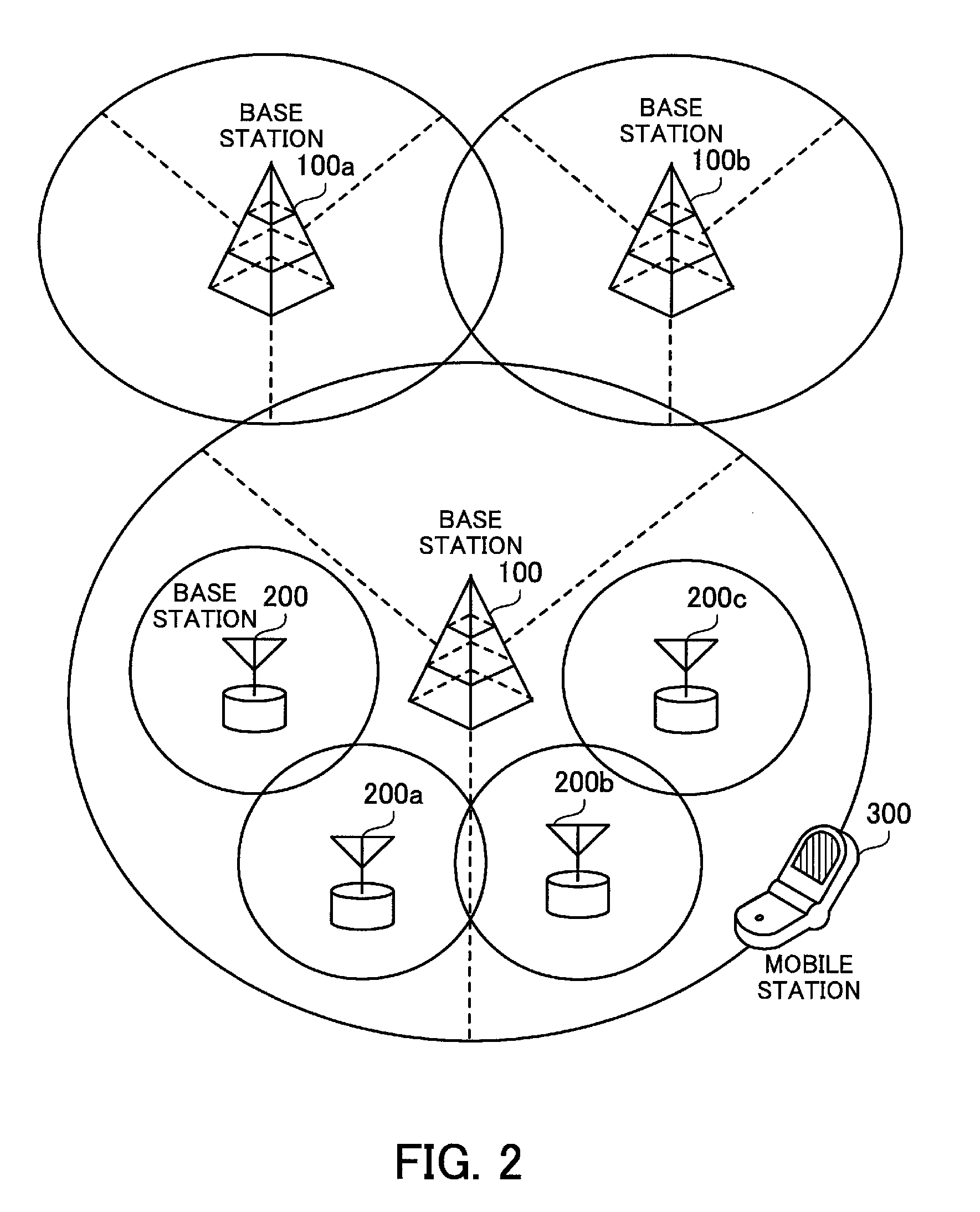
[0028]FIG. 1 illustrates an overview of an embodiment. In a radio communication system of FIG. 1, a plurality of cells are provided in a service area, and a mobile station selects a cell from among this plurality of cells to access in order to perform radio communication. This communication system includes radio base stations 10, 20, and 20a, and a mobile station 30.

[0029]The radio base station 10 is a radio base station that serves a first cell with a large radius. That is, the first cell is a radio coverage area of the radio base station 10. The first cell is equivalent to a macrocell with a radius of 1 to several km. The radio base station 10 is capable of performing radio communication with mobile stations existing in...


PUM


Abstract

In a transmission method, a service area covered by a first cell is provided with a plurality of second cells with a smaller radius than the first cell. A first radio base station belongs to a first cell while the second radio base stations belong to different second cells. A transmitter of the first radio base station transmits a synchronization channel in a given band while a transmitter of each second radio base station transmits a synchronization channel in a band that is different from the given band and also from those of other second radio base stations. A control unit of a mobile station narrows down bands to be observed for detecting synchronization channels to the given band or, if there are some of the second cells that the mobile stations are allowed to access, to the given band and the bands corresponding to the accessible second cells.

Description

[0001]This application is a continuing application, filed under 35 U.S.C. §111(a), of International Application PCT / JP2007 / 070804, filed Oct. 25, 2007.FIELD[0002]An embodiment discussed herein is related to a transmission method, radio base station and mobile station.BACKGROUND[0003]At present, mobile communication systems such as cellular telephone systems and wireless LANs (Local Area Network) are widely deployed. Mostly, cellular-type mobile communication systems are employed. In a cellular type, which is one of the communication forms, a plurality of base stations that serve a set of cells forming a service area are installed, and communications are controlled by these base stations cooperating with each other. A mobile station accesses a cell with good communication quality out of cells that are accessible from where it is now, and performs radio communication.[0004]In order to select an optimal cell, the mobile station performs a cell search. In the cell search, the mobile sta...

Claims


Application Information

Patent Timeline
Patent Type & Authority Patents(United States)
IPC IPC(8): H04W28/16H04J11/00H04J13/00H04W8/00H04W48/12H04W56/00H04W84/04H04W88/08
CPCH04W48/12H04W56/0015H04J11/0069H04J13/0003H04J13/0062H04W8/005H04W28/16H04W84/045H04W88/08H04W72/0453H04W88/02
Inventor TANAKA, YOSHINORI
Owner FUJITSU LTD
Why Eureka
Try Eureka