Auxiliary heating duct for an indirect fired heater

a technology of indirect heating and auxiliary ducts, which is applied in the direction of air heaters, heating fuels, combustion processes, etc., can solve the problems of poor heater performance and poor heater performance in colder climates, and achieve the effect of easy separability and easy mounting on existing heating

Active Publication Date: 2015-02-10
FROST FIGHTER INC
View PDF11 Cites 0 Cited by
  • Summary
  • Abstract
  • Description
  • Claims
  • Application Information

AI Technical Summary

Benefits of technology

[0011]the heating air passage and the combustion passage being separate from one another so as to prevent a flow of combustion gas from the combustion passage from being directed into the heating air passage; and
[0021]the heating air passage and the combustion passage being separate from one another so as to prevent a flow of combustion gas from the combustion passage from being directed into the heating air passage; and
[0027]The auxiliary heating duct is thus arranged for taking a portion of the heated air from the heated air outlet back to the inlet end of the combustion passage to effectively provide some heat to the fuel lines, the burner assembly and the related components to improve the operation thereof in colder climates. By recycling air from the heated air passage back to the burner assembly, there is no concern for combustion fumes entering the heated air passage even when the heated air inlet is located adjacent the combustion inlet.
[0033]The duct may be arranged to be supported on the housing by threaded fasteners such that the duct can be readily mounted onto an existing heating and is also readily separable from the housing.

Problems solved by technology

When used in particularly cold climates, the fuel can gel or other problems may arise from the cold temperatures which result in poor performance of the heater.
Although the temperature of the heated air can be better controlled, the burner assembly and related components remain substantially unheated which can result in poor performance of the heater in colder climates as described above.

Method used


Image

  • Auxiliary heating duct for an indirect fired heater
  • Auxiliary heating duct for an indirect fired heater
  • Auxiliary heating duct for an indirect fired heater

Examples


Embodiment Construction

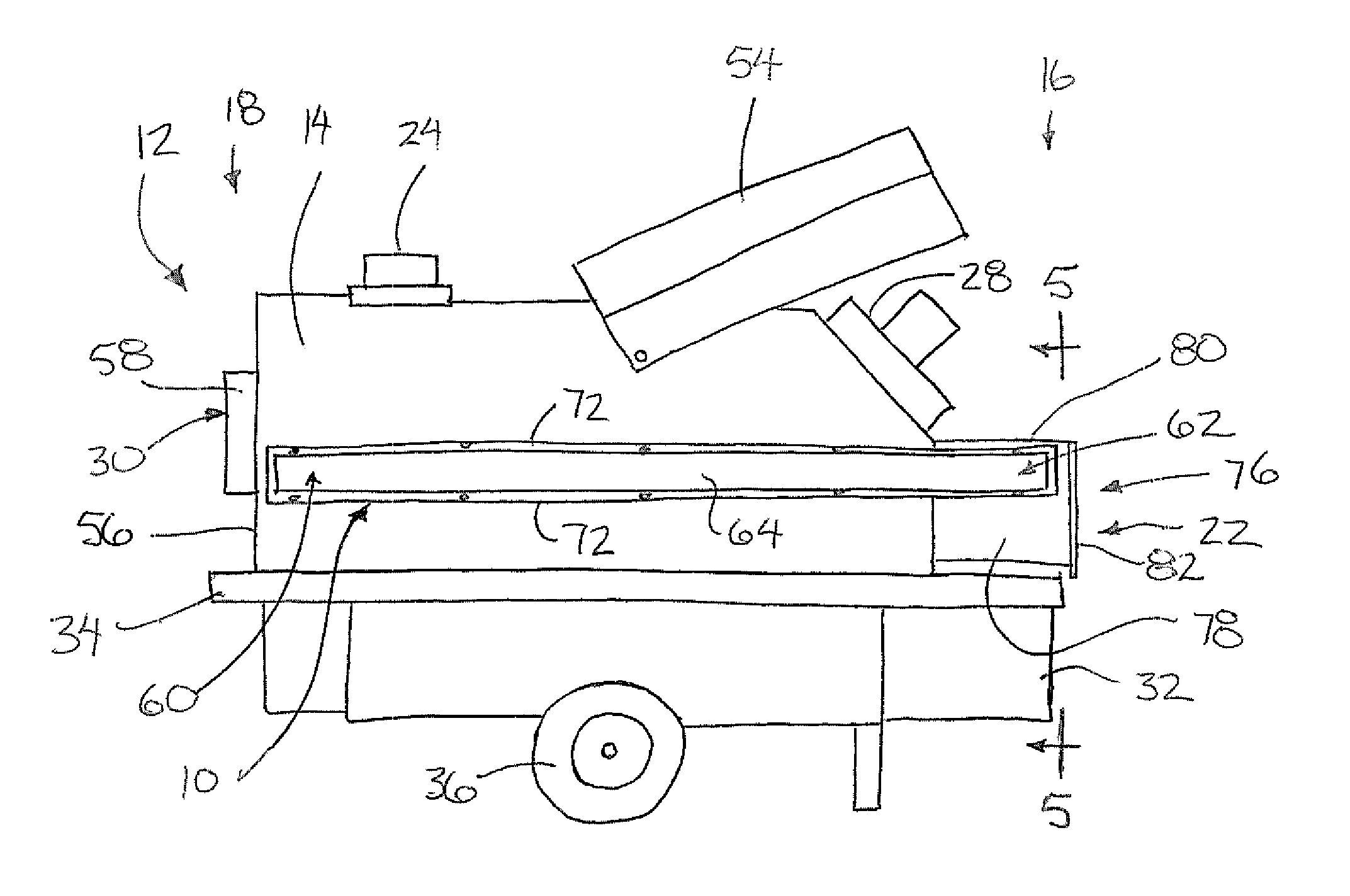
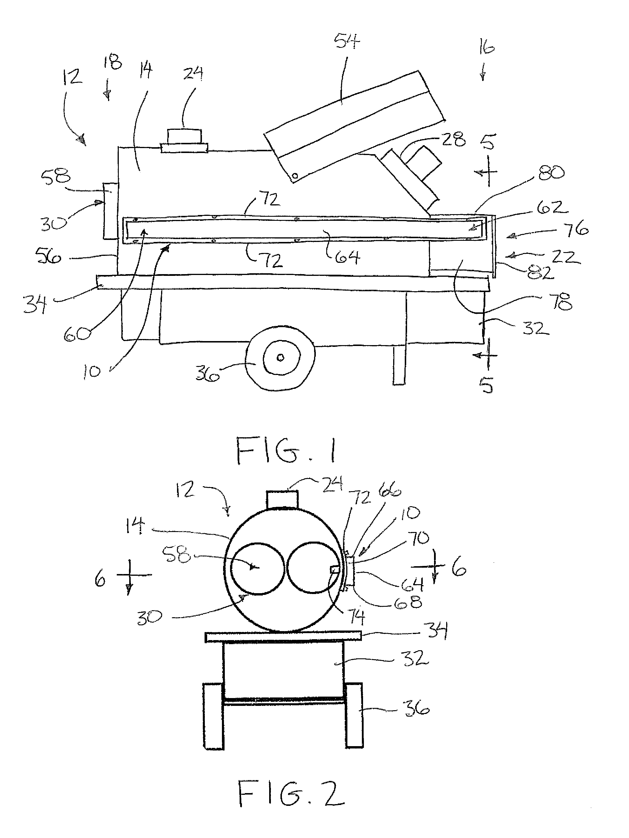
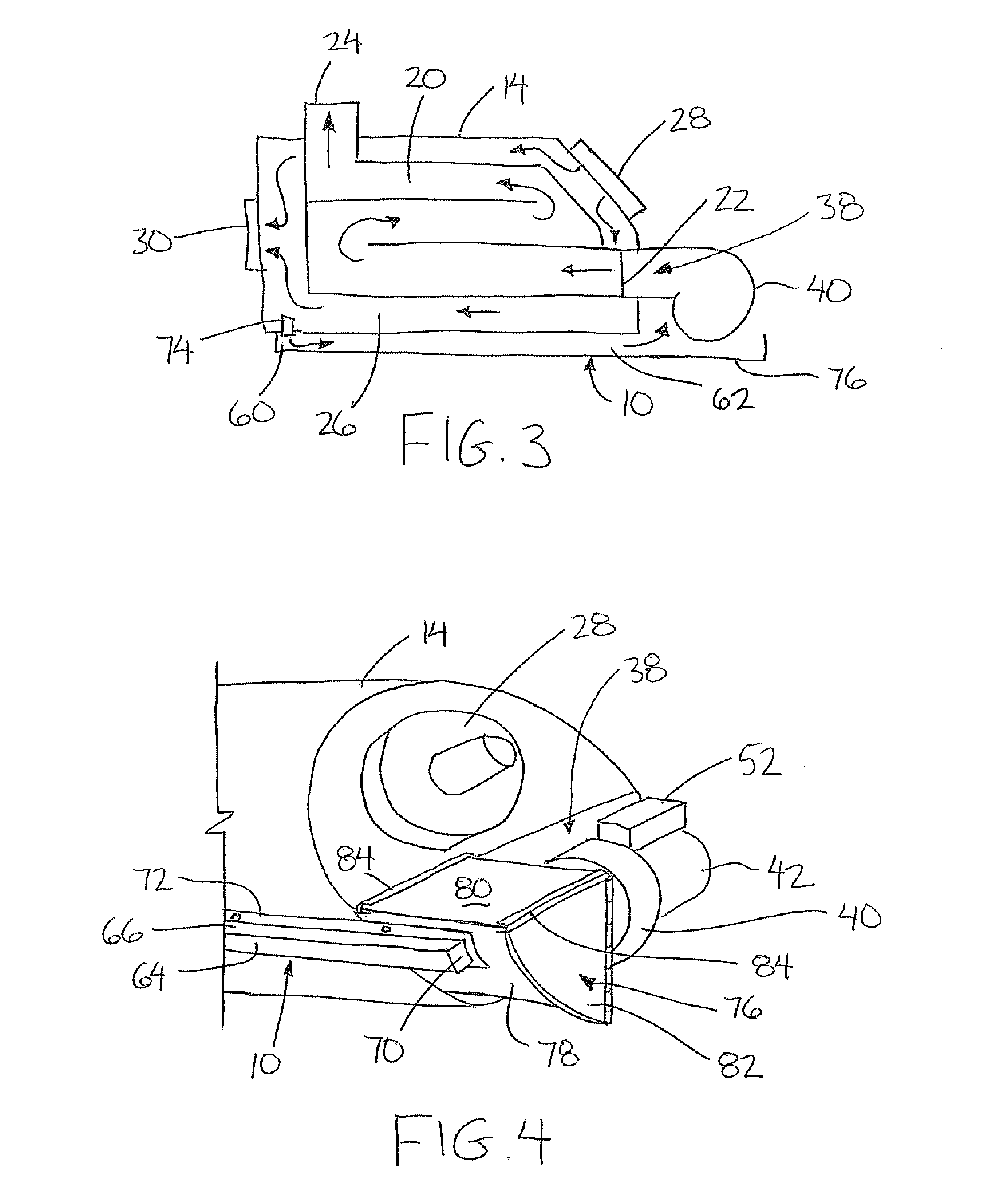
[0043]Referring to the accompanying figures, there is illustrated an auxiliary heating duct generally indicated by reference numeral 10. The duct 10 is particularly suited for use with an indirect fired heater 12 to improve the performance of the burner assembly and related components when used in colder climates.

[0044]According to the illustrated embodiment, the duct 10 is suited for a heater of the type comprising a housing 14 having a generally cylindrical peripheral wall which is elongate in the longitudinal direction between a first end 16 and an opposing second end 18 of the heater. The housing locates a combustion passage 20 extending therethrough from an inlet 22 at the first end 16 to an outlet 24 extending upwardly through the top end of the housing adjacent the second end thereof. The housing further locates a heating air passage 26 extending from an inlet end 28 adjacent the first end of the heater to an outlet end 30 adjacent to the second end of the housing similar to ...


PUM


Abstract

An auxiliary duct is supported on the housing of an indirect fired heater of the type having separate heated air and combustion passages. The auxiliary duct extends between an inlet end at the heated air discharge to an outlet end adjacent a burner assembly at the combustion inlet so as to be arranged to direct a portion of the flow of air heated by the heater towards components of the burner assembly including fuel lines, a fuel pump, a fuel filter and a combustion air intake blower for heating the burner assembly and associated components to improve the operation thereof in colder climates.

Description

[0001]This application claims foreign priority benefits from Canadian Patent Application 2,738,721 filed Apr. 26, 2011.FIELD OF THE INVENTION[0002]The present invention relates to an auxiliary duct for use with an indirect fired heater comprising separate heated air and combustion passages in which the auxiliary duct is arranged to direct a portion of the heated air towards components of the burner assembly adjacent the inlet end of the combustion passage. The present invention thus relates to a duct for directing heated air towards the burner assembly for heating the burner assembly and related components to improve the operation thereof in colder climates.BACKGROUND[0003]A common type of portable heater for temporary use, for example at construction sites or remote work sites in the oil and gas industry, is an indirect fired heater. In this instance, the heated air is clean and free of moisture and contaminated fumes so as to be suitable for areas where persons are working.[0004]U...

Claims


Application Information

Patent Timeline
Patent Type & Authority Patents(United States)
IPC IPC(8): F24H3/00F23L15/00F24D5/02F24D15/02F24H3/06
CPCF23L15/00F24H3/06F24D5/02F24D15/02F24H3/0417F24H3/006Y02E20/34
Inventor FROESE, RODNEY A.ISAAC, DARREN R.
Owner FROST FIGHTER INC
Why Eureka
Try Eureka