Apparatus and method for heating ground

a technology of ground heating and apparatus, applied in the direction of combustion process, other heat production devices, insect catchers and killers, etc., can solve the problems of few services buried, ineffective summer equipment for penetrating the surface, waste of energy, etc., and achieves efficient heating and deep thawing. , the effect of complex thawing patterns and more uniform heating or thawing

Active Publication Date: 2013-10-01
BEFUS DALE
View PDF6 Cites 4 Cited by
  • Summary
  • Abstract
  • Description
  • Claims
  • Application Information

AI Technical Summary

Benefits of technology

[0015]In some embodiments, the apparatus and method presented herein can provide means for efficiently providing heating and deep thawing in a modern construction environment. In some embodiments, dimensionally fixed, unitized heaters are provided that can collaborate in arrays to evenly thaw a surface in a desired dimension in a timely manner. Accordingly, these unitized heaters can be used like “building blocks” and positioned to achieve the individual and collaborative thaw patterns desired. In some embodiments, individual arrays of the heaters can collaborate to achieve very complex thaw patterns.
[0016]In some embodiments, infrared radiant heaters can be used alone or in conjunction with other components and techniques for achieving more uniform heating or thawing. Such components and techniques can include increasing the surface area of radiating conduit by such strategies as double tubing. In some embodiments, the heaters can be enclosed with highly reflective material in order to scatter the reflected radiant energy over the entire target ground surface. In some embodiments, fans or blowers can be provided to help ensure that the heat is more efficiently and evenly radiated within the heater enclosure.
[0017]In some embodiments, the apparatus and method presented herein can achieve a similar or better heating or thaw depth with superior dimensionality to other conventional methods within comparable heating or thawing times over a broad range of climatic conditions. To achieve these goals, the apparatus, in some embodiments, can be configured to collaborate in arrays. In contrast to the conventional ground-heating methods wherein heat energy is produced in one location and transported to the zone of interest by gas or fluid, the apparatus presented herein can be configured such that each part of the overall spatial dimension of ground to be heated can be supplied with a heat source of predictable heat or thaw dimension. In some embodiments, each heater can provide more uniform deep heating or thawing within its footprint on the surface on the ground without loss to distal heating or thawing. When placed adjacent to other heating devices of defined dimension, the unitized fixed-form heating devices can overlay the heat or thaw areas as defined in construction plans similar to the concept to of setting out building blocks. By this method, the heaters can collaborate to provide maximal heat for deep heating or thawing within the dimension of the array of devices and heating or thawing of unnecessary ground is minimized. No energy is lost from transporting heat from an external energy source (e.g. a furnace or boiler) to the heat or thaw zone as used in other conventional prior art heating apparatuses and methods.
[0019]In some embodiments, the apparatuses and methods described herein can be used to pre-heat the ground for a construction activity. One example can include pre-heating asphalt around a pothole on a road to enable new asphalt used to fill the pothole to bond to the surrounding asphalt and thus produce a better repair of the pothole. Other examples can include heating the ground prior to adding new or additional ground material where heating the ground improves the adhesion of the new or additional ground material to the existing ground material.

Problems solved by technology

In cold climates, frost persists in the ground for much of the year rendering summertime equipment for penetrating the surface (e.g., digging, trenching, ploughing, filling, sealing, and the like) ineffective without first thawing the ground.
However few services are buried at such depths and many services are situated deep within the frost zone.
Consequently, controlling the dimension of the thaw has become increasingly important as too little thawing at the required dimension and depth leads to difficulty moving the earth as desired while too much thawing may cause problems such as wasted energy or sloughing of the adjacent terrain.
Meeting these regulations is often challenging and expensive.
When used for deep thawing, the downward radiation and conduction is a relatively small part of the energy output; thus, the technique can be slow and may result in uneven thawing at target depths.
Moreover, this technique can lead to significant loss of energy over the length of the hoses or pipes, especially when the heat source is far from the thaw zone.
Uneven distances between these conduits may also result in uneven heating throughout the target thaw zone.
At any given construction site, one or more of these limitations may result in difficulty in planning or meeting schedules.
Similarly, when one heats an indoor air environment inside of shrouding or a canopy, the working environment may comfortable and enclosed surfaces compliant to best practices for curing, sealing and the like but ground thawing is superficial and normally not dimensionally compliant to the enclosure at depth.
This result may be magnified in harsh conditions as the susceptible to the elements of weather wherein colder or faster moving air absorbs the energy the contractor wants focused on the target ground.
Again, any of these complications may result in a contractor having difficulty planning or meeting schedules.
Because of its size and trailer mount, the unit is difficult to place between structures (for example between a garage and a fence) and cannot be used in contiguous arrays that would thaw ground for contiguous underground structures such as gas or electrical service.
The external burner limits its use near building structures and trees and results in the production of waste heat.
Accordingly, this device does not predictably allow trenching of the entire dimension of the case footprint in a period less than 48 top 72 hours.
Moreover, if placed end to end to enable the digging of a 48″ wide trench, for example, the external burner box and inverted conical thawing at depth would result in intermittent segments where there is difficult digging in frozen ground.
When temperature dropped rapidly overnight, the inability to capture heat and direct the heat downward often resulted in incomplete thawing within the production schedule.
This technique also suffered from intermittent loss of ignition by vandalism, rain, snow, melt water or discontinuities in fuel as well as pollution through emission of smoke, cinders, and odor.
Even with monitoring, the combination wind and cinders, left an ever-present fire hazard.
Accordingly, this technique was particularly unsafe for use near construction equipment, buildings, as well as in dry fields, or wooded areas.
If there were delays between burning and trenching, the local microenvironment was uncontrolled resulting in the potential for refreezing.
Accordingly, all conventional deep-thawing practices suffer the common problem of scheduling reliably.
None of the above-mentioned methods reliably leave a dimensionally uniform thaw zone at a predictable time.

Method used


Image

  • Apparatus and method for heating ground
  • Apparatus and method for heating ground
  • Apparatus and method for heating ground

Examples


Embodiment Construction

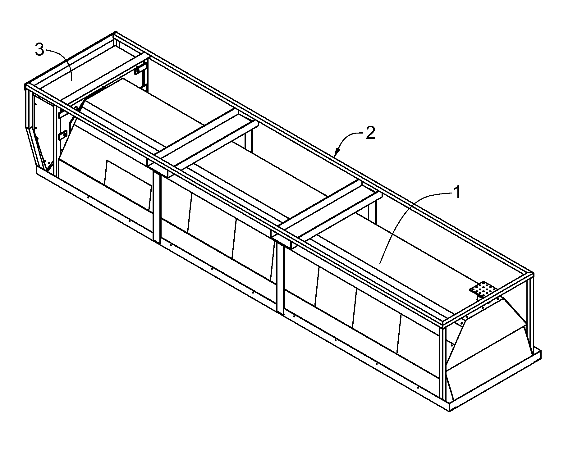
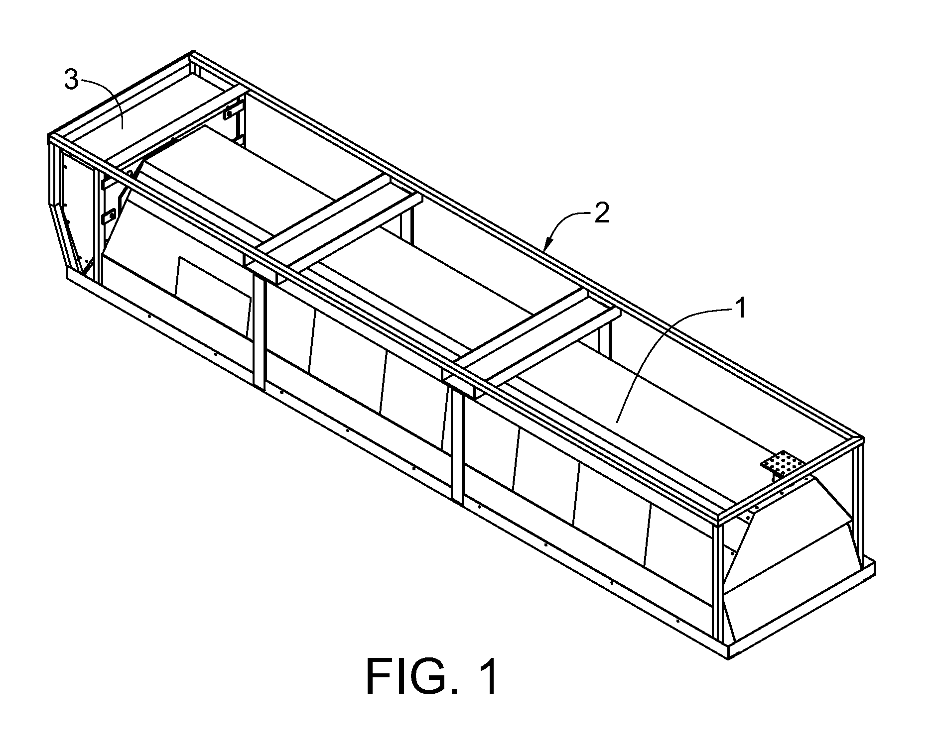
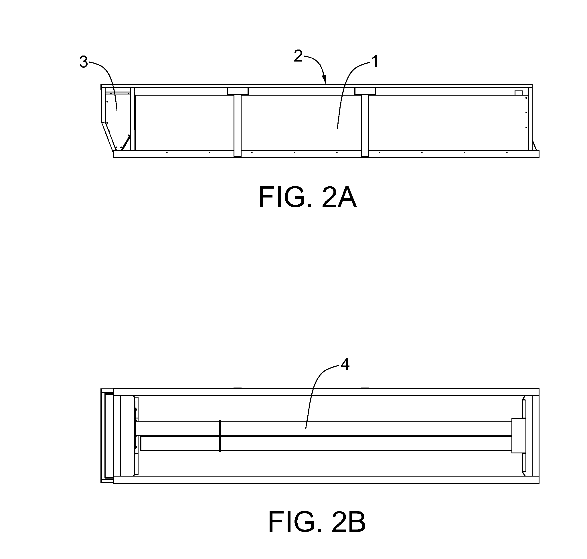
[0044]An apparatus and method for thawing frozen ground is provided herein. In some embodiments, the apparatus and method can comprise one or more unitized thawing devices, means for transporting the devices, and means for controlling the devices as well as the components for the system.

[0045]For the purposes of this application, the following terms are defined as follows.

[0046]“Array”—means devices arranged for heating thawing the ground in dimensional conformance with all or part of an existing or planned surface or subsurface structure. These devices may share one or more energy sources to achieve a desired collaborative effect. Where the surface target is not rectangular, placing a group of rectangular arrays or sub arrays adjacent to each other can form a thawing system. In the alternative, combinations of devices including non-rectangular shaped devices can be employed.

[0047]“Device” means a unitized fixed-form ground-heating device configured for heating or thawing the ground...


PUM


Abstract

An apparatus and method is provided for preparing frozen ground for construction-type work includes using arrays of heat sources placed over the surface to be heated. The apparatus can warm the surface in preparation for the construction activity with energy penetrating into the ground affording efficient thawing of materials below 20 centimeters of depth. Heat sources used in the array can include emitted infrared radiation.

Description

PRIORITY STATEMENT & CROSS-REFERENCE TO RELATED APPLICATIONS[0001]This application claims priority from U.S. Patent Application No. 61 / 533,357, entitled “Apparatus and Method for Heating Ground” and filed on Sep. 12, 2011, in the name of Dale Befus; which is hereby incorporated by reference for all purposes.TECHNICAL FIELD OF THE INVENTION[0002]The present disclosure is related to the field of ground heating equipment, in particular, radiant heaters used for heating ground and for thawing frozen ground.BACKGROUND OF THE INVENTION[0003]Much construction in modern economies lie in building, installing, and maintaining surface and subsurface structures such as roads, water distribution, drainage systems, pipelines, barriers, fences, electrical transmission infrastructure, telecommunication infrastructure, and the like. In cold climates, frost persists in the ground for much of the year rendering summertime equipment for penetrating the surface (e.g., digging, trenching, ploughing, fill...

Claims


Application Information

Patent Timeline
Patent Type & Authority Patents(United States)
IPC IPC(8): F24J3/08
CPCE01C23/14F28D2021/0019
Inventor BEFUS, DALE
Owner BEFUS DALE
Why Eureka
Try Eureka