Heated insoles

a technology of insoles and soles, which is applied in the direction of soles, electric vehicles, transportation and packaging, etc., can solve the problems of exposing the charging components to heat and mechanical stress of use, and the current design, while conventional, is limited

Active Publication Date: 2017-01-17
SCHAWBEL TECH
View PDF142 Cites 3 Cited by
  • Summary
  • Abstract
  • Description
  • Claims
  • Application Information

AI Technical Summary

Benefits of technology

[0012]Another object of this invention is to more efficiently provide heat to the wearer during normal usage.
[0014]Yet another object of this invention is to provide a more efficient, economical system for heating insoles.
[0015]Another object of this invention is to more efficiently locate the heater within an insole to more directly provide heat to the foot of the wearer.
[0016]Yet another object of this invention is to provide a more efficient and economical battery charging system more susceptible of widespread use.
[0019]Since the IC is a relatively expensive part of the lithium battery assembly, removing it from the physical wear and tear conventionally encountered and integrally formed with the battery to be charged enables a costly component to prolong its life, reduce the possibility of failure and ensure that only the lithium battery is replaced when necessary without the need to replace the entirety of the Intelligent Circuit (IC) lithium battery combination.
[0020]Further, the above objects are accomplished by additionally relocating the heater within the insole from the substantially bottom most location furthest from the foot of the user to a location closer to the foot of the user so as to provide more efficient heat directed to the user, thereby reducing power drain and more efficiently and quickly heating the area. Prior art insoles have an EVA foam layer of about 5 mm thickness located above the heater. The new structure compresses the EVA foam to no more than 2 or 3 mm, then adds an additional conductive layer above the battery and an additional insulating layer between the foot and bottom of the shoe to improve heat conductivity to the foot of the wearer.

Problems solved by technology

Current designs, while conventional, are limited in that a good portion of the heat is not provided to the upper portion of the sole, which is in closer contact with the foot of the wearer.
This arrangement subjects the charging components to the heat and mechanical stress of use when the footwear is worn.
Any failure of a charging component renders the entire product useless.

Method used


Image

  • Heated insoles
  • Heated insoles
  • Heated insoles

Examples


Embodiment Construction

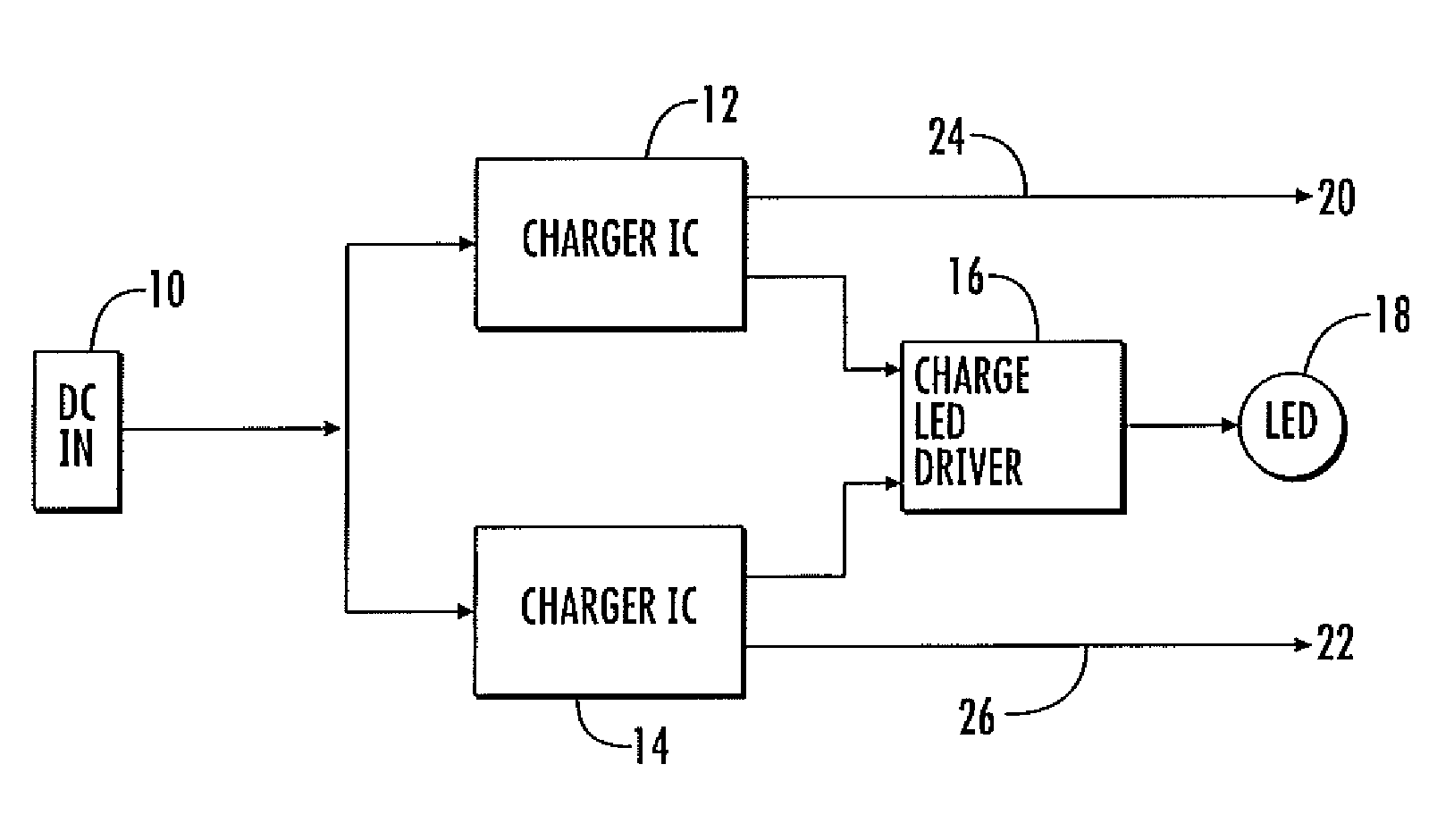
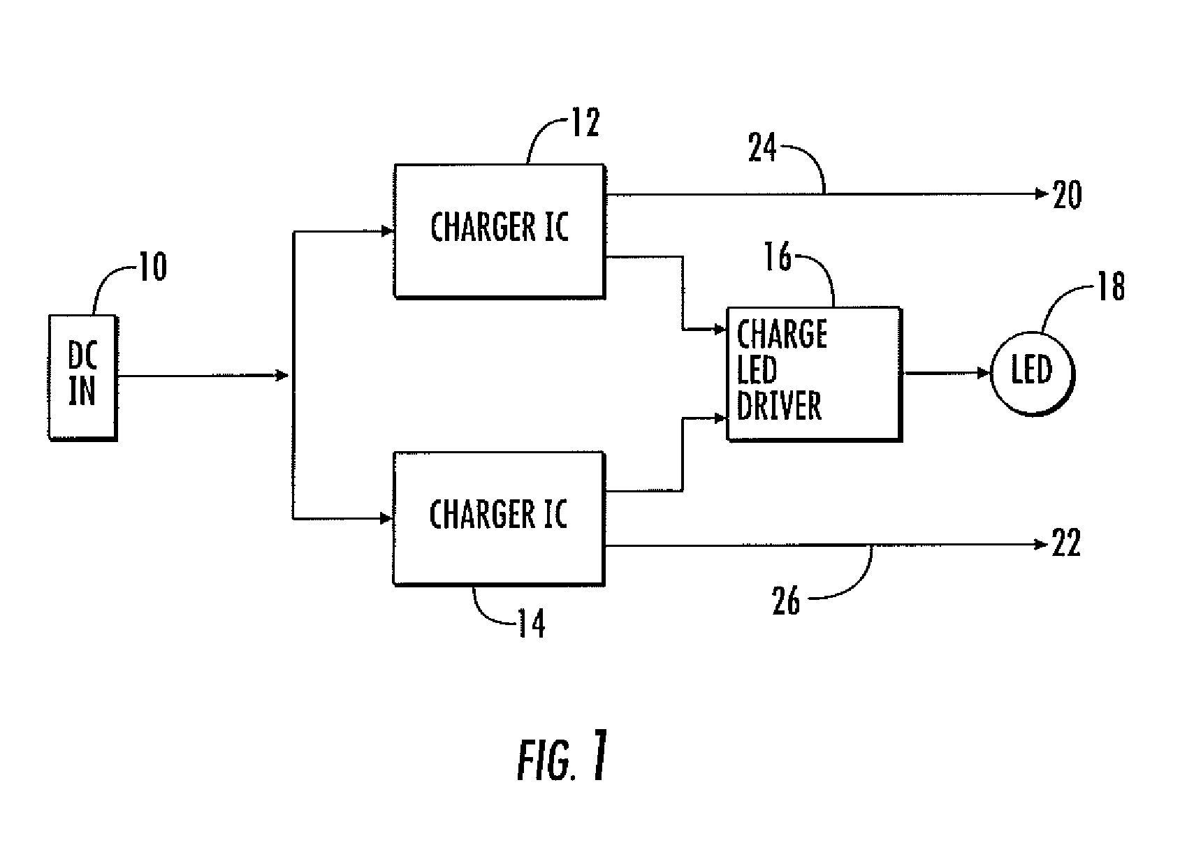
[0028]FIG. 1 is a block diagram of this invention with the AC to DC converter merely indicated as DC in block 10. Such AC to DC converter is plugged into a 120 volt wall socket or any other suitable AC wall socket to provide a DC output. The output of the DC converter 10 is supplied to charger intelligent circuits (IC) 12 and 14 which include the ability to receive the low DC voltage produced by converter 10, monitor the battery charge state and deliver suitable current and voltage to fully and safely charge the batteries. A charge LED driver 16 is provided to light an LED 18 as the batteries are being charged. The output of the charger intelligent circuits 12 and 14 are supplied to batteries 20 and 22 respectively, which are separately located within the insole.

[0029]Batteries 20 and 22 are located within the insoles, and two batteries are provided for the pair of insoles for the pair of shoes. Cables or conductors 24 and 26, respectively, are provided as outputs of the IC circuits...


PUM


Abstract

An efficient system to heat the insole of a heated insole of a shoe in which the Intelligent Circuit (IC) for a flat lithium battery is located outside the shoe and the placement of the heater for the insole is between more efficient heat insulation and heat conducting members.

Description

RELATED APPLICATIONS[0001]This application is based upon two U.S. Provisional Patent Applications, Ser. Nos. 61 / 581,782, filed Dec. 30, 2011 and 61 / 594,043, filed Feb. 2, 2012, the priority of which are claimed and the contents of which are incorporated herein.DESCRIPTION AND BACKGROUND OF THE INVENTION[0002]This invention relates to improvements for heated insoles for shoe wear, especially for hiking, cycling and skiing and even for ordinary shoes if the wearer has cold feet.[0003]Over the years, various systems have been designed and employed to provide additional heat inside shoes when they are used in outdoor environments. An example of such a prior art system is shown in US Patent Publication US2009 / 0013554, which is directed to a wireless system in which signals are transmitted to control a heater in the insole.[0004]For some time, there have been fixed hardwired systems such as shown in U.S. Pat. No. 4,665,301 in which heaters are plugged into a wall socket to provide heat to...

Claims


Application Information

Patent Timeline
Patent Type & Authority Patents(United States)
IPC IPC(8): H02J7/00A43B3/00A43B3/35
CPCH02J7/0052A43B3/0005A43B3/34H02J7/00
Inventor SHAPIRO, STEPHENLYNCH, JAMES K.WHITEHEAD, IAN NICHOLSON
Owner SCHAWBEL TECH
Why Eureka
Try Eureka