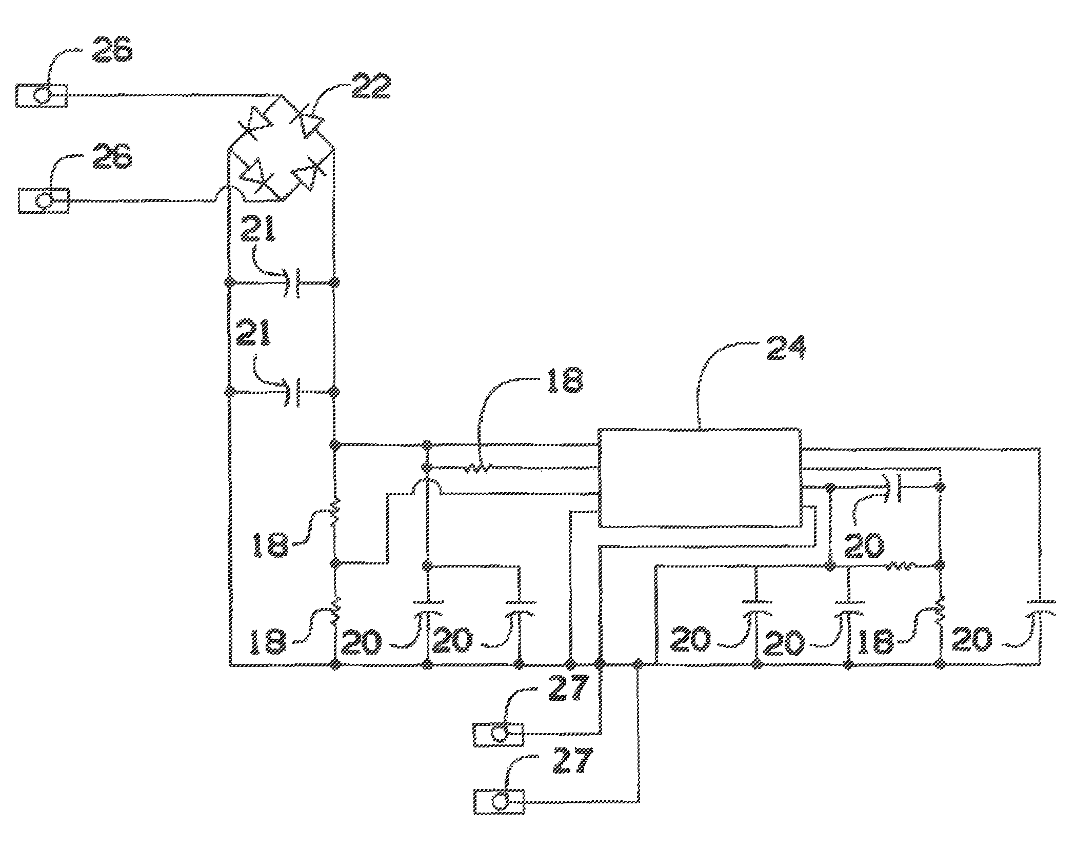
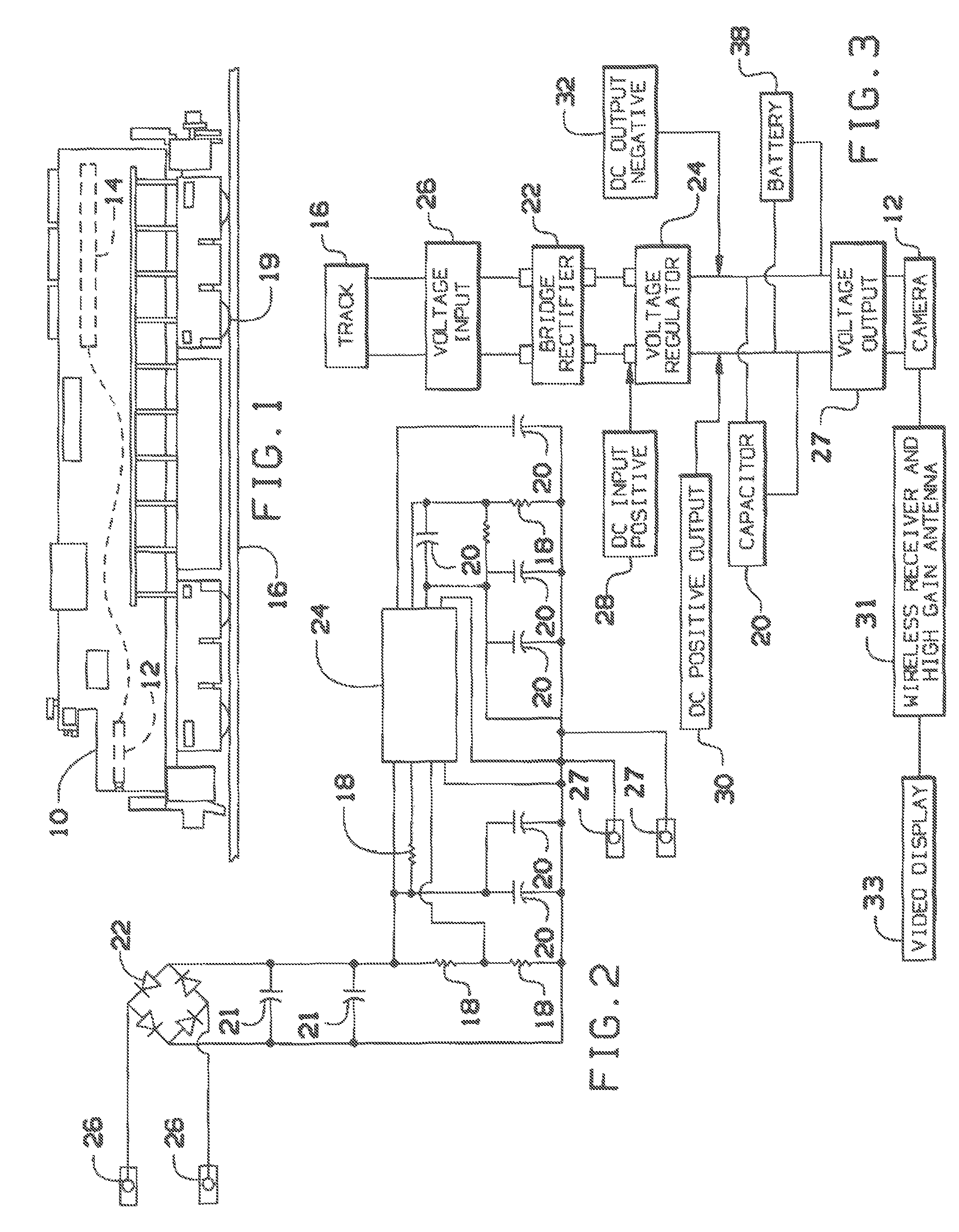
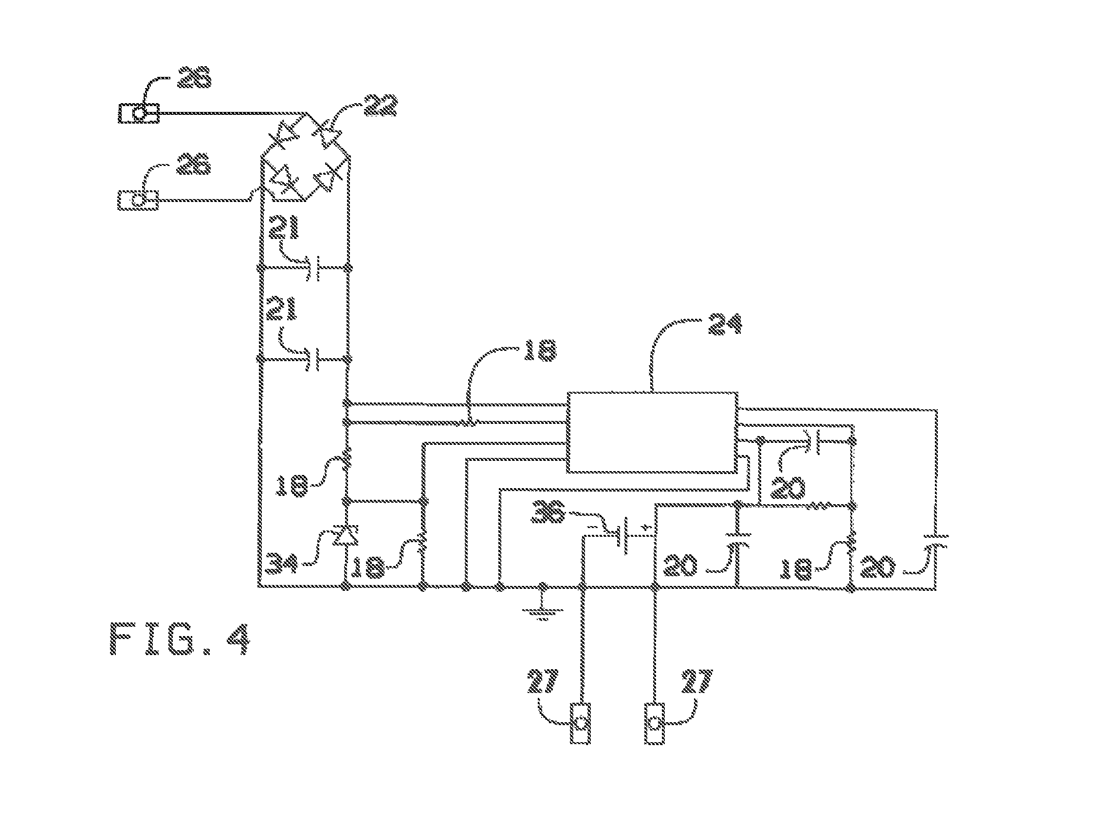
[0016]FIG. 1 shows a side view of a typical model railroad engine with the modifications of the present invention inserted. The location of camera 12 and the power supply circuit 14, illustrates one possible location depending upon the design of the engine 10. N and HO gauge engines as in FIG. 1, have one camera 12, but our power supply circuit 14 has the capability to power two or more cameras; for instance one camera pointing forward and one camera pointing backwards. In this configuration the view from the railroad engine 10 will be coming and going at the same time. As such, the power supply circuit 14 as shown in FIG. 1 was designed to minimize the footprint to afford greater flexibility for placement and positioning in the various available model railroad engine designs from different locomotive model manufacturers. The engine is supported by tracks 16 and wheels 19 conduct electrical power (either AC or DC) from the track 16 to power the power supply circuit 14
[0017]FIG. 2, of the present invention receives power from the connectors 26 to a bridge rectifier 22 and one or more capacitors 21 between 22 and the remainder of the circuit to serve as buffering. The one or more capacitors 21 also store electrical power that is used in the event that the model railroad engine passes over areas of a track that have poor electrical contact. Voltage regulator 24 refers to a preferred type of voltage regulator that dissipates excess voltage by increasing amperage output rather than dissipating the energy as heat. This affords the circuit design of the present invention much greater longevity both in terms of real-time periods of usage as well as extended lifetime of the components. FIG. 2 shows a power supply circuit 14 compatible with camera systems with readily available AC adapters that do not match the needs of the camera 12. In these a step-down circuit is included with the camera 12, which produces appreciable heat. Thus, this design is for use with the commercial camera 12 receiving power from output connectors 27 with all of the camera 12 circuitry intact. The remainder of the power supply circuit 14 consists of a network of resistors 18 and capacitors 20 that were empirically selected.
[0018]FIG. 3 is a block diagram of the present invention. Power is conducted from the track 16 to the engine 10 through the wheels 19 and then providing a voltage input 26 as shown in FIGS. 2 and 4. Then, electricity flows through a bridge rectifier 22, and emerging as a DC positive input 28 and negative input (un-shown) and then into the voltage regulator 24 emerging as DC positive output 30 and DC negative output 32. One or more output capacitors 20 as shown in FIG. 2 and FIG. 4 and a commercial rechargeable battery (or chip battery) 38 which is recharged by the output of the power supply circuit 14, all of which maintain a constant output for the camera(s) 12 input. The camera transmits video images on a carrier wave via a built in antenna (un-shown). The modulated video images are received by an antenna attached to a wireless receiver, which may be a high-gain antenna 31. The commercial high-gain antenna 31 increases the signal to noise ratio where other wireless devices are in close proximity to the camera system. Lastly, the receiver output is a signal that may be either displayed on a video display 31 or alternatively on a monitor/TV or on any video system.
[0019]FIG. 4 shows another embodiment that reduces the heat output found in the first circuit seen in FIG. 2, and delivers the exact voltage that the camera 12 needs without the step-down circuit. This embodiment also substitutes resistors 18 and capacitors 20 that have different output values and a diode 34 that differ from those found in the circuit seen in FIG. 2. Moreover, some of the components illustrated in the design in FIG. 2 were found to be unnecessary for the direct output circuit and have been removed. FIG. 4 also shows a battery 36, which is rechargeable by the output of the switching regulator 24, thereby maintaining a constant output to the camera 12 in the event power to the power supply circuit 14 is interrupted. In like manner, the battery 36 may also be inserted into the power supply circuit 14 found in FIG. 2 in the same position of the circuit to serve the same function. The remainder of the power supply circuit 14 consists of a network of resistors 18 and capacitors 20 that were empirically selected. Connectors 26 supply power at the input to the bridge rectifier 22 and connectors 27 provides output from the power supply circuit 14 directly to the camera bypassing the camera step-down circuit. The present invention allows the hobbyist to retrofit their existing engines with easily installed kits. Model Railroad suppliers can also provide our Engineer's View system as a factory-installed option in various locomotives using the present invention.