Kinematic platform

a technology of kinematics and platforms, applied in the field of kinematic platforms, can solve the problems of large positioning errors at the end effector, poor stiffness to mass ratio, and bulky structure design

Inactive Publication Date: 2015-02-17
KING FAHD UNIVERSITY OF PETROLEUM AND MINERALS
View PDF31 Cites 28 Cited by
  • Summary
  • Abstract
  • Description
  • Claims
  • Application Information

AI Technical Summary

Problems solved by technology

Unfortunately, this results in large positioning errors at the end-effector.
Being constructed of cantilevers, a serial mechanism has a poor stiffness to mass ratio, making such structures bulky in design with difficult in control of the joints.
However, determining the position or state of all actuators given the position of the end-effector, also known as the inverse kinematics, is very difficult.
Such mechanisms are usually very complex and due to the manual locking are not suitable for robotic or parallel kinematic machine operations.
Even lockable joint devices linked to hydraulic systems may not be suitable for robotic applications, or the like.
Moreover, ball joints with detent stopping action do not lock to an arbitrarily desired position, and therefore are not precise enough for robotic machine applications.

Method used


Image

  • Kinematic platform
  • Kinematic platform
  • Kinematic platform

Examples


Embodiment Construction

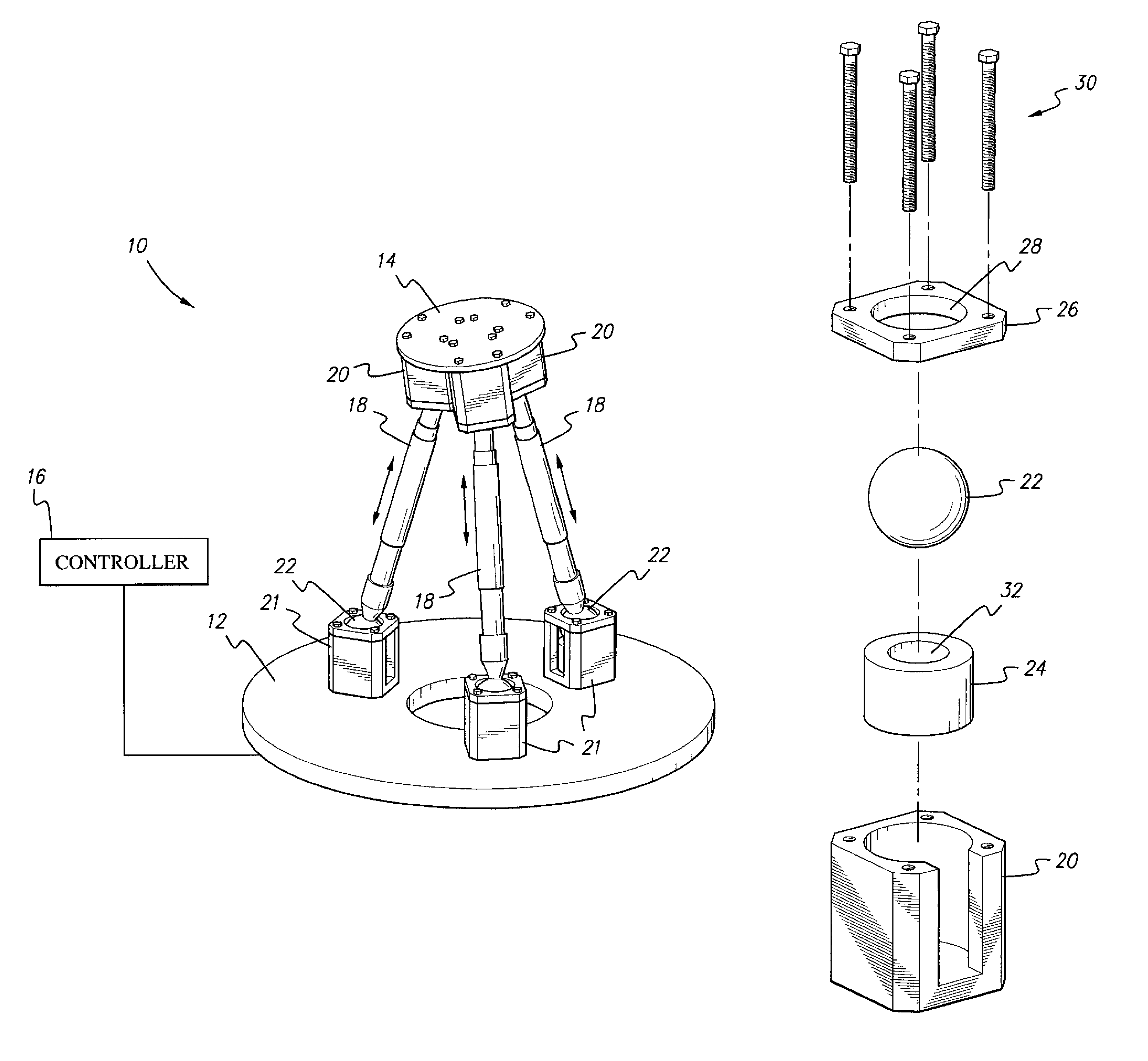
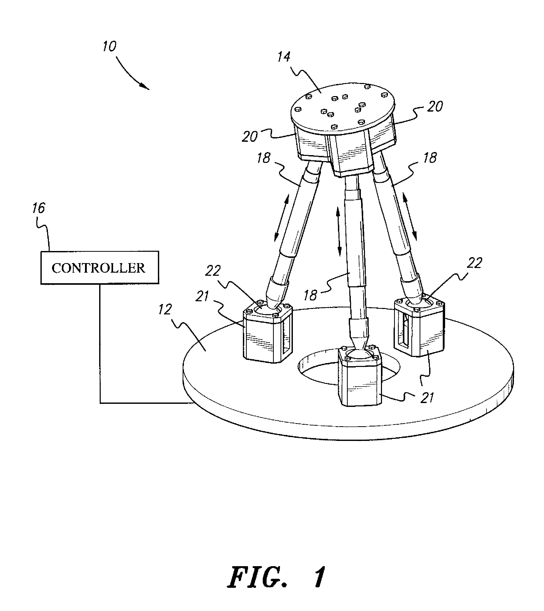
[0021]As best shown in FIG. 1, the kinematic platform 10 is a kinematic platform providing six degrees of freedom with controlled braking at each joint. The kinematic platform 10 includes a base 12 having opposed upper and lower surfaces, the lower surface being adapted for mounting on a support surface, such as a table or the like. An upper platform plate 14 is further provided, with the upper platform plate 14 having opposed upper and lower surfaces. The upper surface of the platform 14 provides a mounting surface for an external article to which controlled three-dimensional movement is to be imparted.

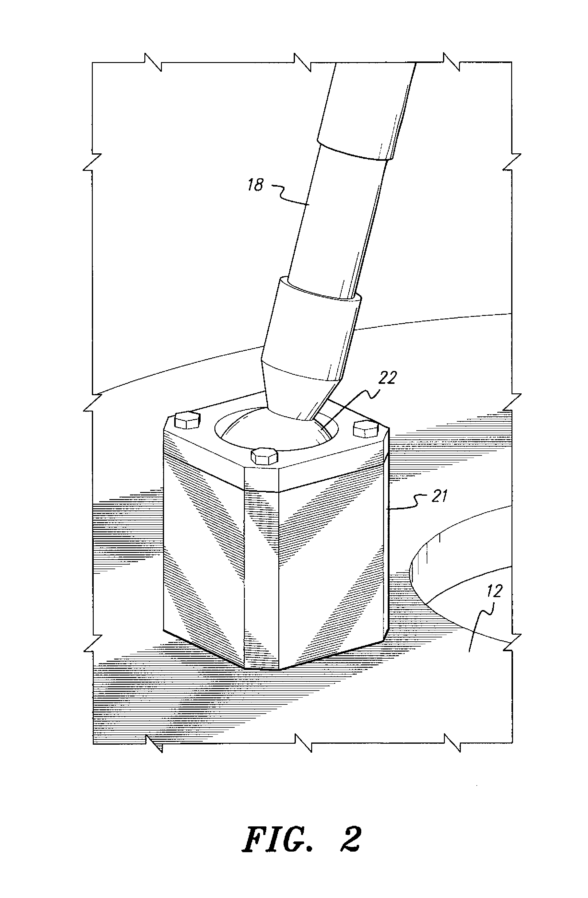
[0022]A plurality of linear actuators 18 which may be actuated electrically, pneumatically, hydraulically, etc.) are further provided, each linear actuator 18 having opposed upper and lower ends. Preferably, at least three such linear actuators 18 are provided, and, in the preferred embodiment, the linear actuators 18 may be selectively actuated by an external controller 16. It shoul...


PUM


Abstract

The kinematic platform is a spherical-prismatic-spherical kinematic platform providing six degrees of freedom with controlled braking at each joint. The kinematic platform includes a base and an upper platform plate, with the upper platform plate having opposed upper and lower surfaces. The upper surface thereof provides a mounting surface for an external article to which controlled three-dimensional movement is to be imparted. A plurality of linear actuators are further provided, with each linear actuator having opposed upper and lower ends. A plurality of upper and lower spherical joints are provided for pivotally mounting the linear actuators between the upper platform plate and a lower base. Each spherical joint provides selective and controllable braking, allowing for the controlled rotation of each end of each linear actuator with respect to the respective upper platform plate or base.

Description

BACKGROUND OF THE INVENTION[0001]1. Field of the Invention[0002]The present invention relates to movable or adjustable platforms and to tripods, and particularly to a kinematic platform having three legs providing six degrees of freedom with controlled braking at each joint and high dexterity within the workspace.[0003]2. Description of the Related Art[0004]A need exists for simple and effective parallel kinematics mechanisms. Kinematics mechanisms are used in mechanical engineering applications for machining, robotics, positioning devices, coordinate measuring, fixtures, etc. Serial kinematics mechanisms are widely used and presently dominate the market. A serial kinematics mechanism has a series of cantilever beams that are movably connected together in an end-to-end fashion by prismatic, revolute or spherical joints, forming an open loop. The closer that a member is to a base of the mechanism within the serial structure, the higher the load on that member. Additionally, the farth...

Claims


Application Information

Patent Timeline
Patent Type & Authority Patents(United States)
IPC IPC(8): F16C11/00F16M11/04F16M11/12F16M11/14F16M11/18
CPCF16M11/14F16M11/043F16M11/121F16M11/18Y10T74/20317Y10T403/32631Y10T403/32672Y10T403/32721
Inventor MEKID, SAMIRKHALID, AZFAR
Owner KING FAHD UNIVERSITY OF PETROLEUM AND MINERALS
Why Eureka
Try Eureka