
Tubular member extrusion method and tubular member extrusion apparatus

Active Publication Date: 2015-02-17
TOYODA GOSEI CO LTD
View PDF20 Cites 3 Cited by
  • Summary
  • Abstract
  • Description
  • Claims
  • Application Information

AI Technical Summary

Benefits of technology

The invention is a method for making an extruded tubular member by controlling the position of a core-side die in relation to an extrusion orifice. This allows for the creation of tubular members that have a variety of shapes and radii of curvature, without requiring a mandrel and resulting in improved productivity. Additionally, the core-side die has an inclined plane that simplifies the process of changing the circumferential contact area.

Problems solved by technology

In the steps in which the metallic mandrel is used, since the placement of the hose intermediate on the mandrel and removal of the vulcanized hose from the mandrel are manually performed, there is caused a problem that these steps are troublesome.
However, even in the event of this technique being applied, there has still been a problem that a three-dimensional complicated bent configuration cannot be dealt with.Patent Document 1: JP-A-10-263682

Method used


Image

  • Tubular member extrusion method and tubular member extrusion apparatus
  • Tubular member extrusion method and tubular member extrusion apparatus
  • Tubular member extrusion method and tubular member extrusion apparatus

Examples


Embodiment Construction

(1) Schematic Configuration of a Hose H Having a Bent Configuration

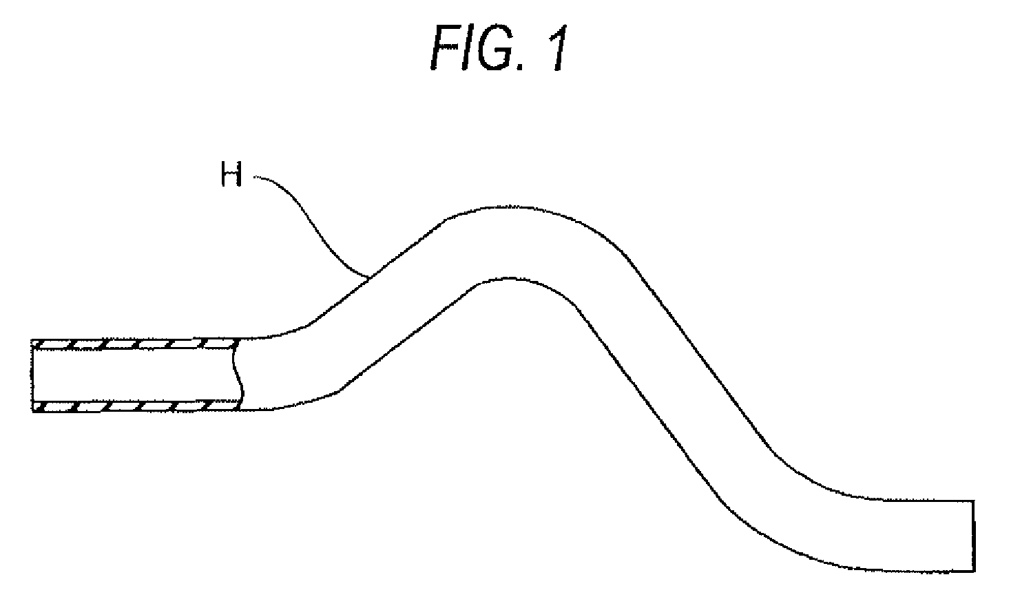
[0026]FIG. 1 is an explanatory diagram which explains a hose that is fabricated by a hose (tubular member) extrusion method according to an embodiment of the invention. A hose H is, for example, a rubber hose that is used in a location where a radiator and an engine is connected and is bent into a three-dimensional configuration to mach a disposition path within an engine compartment. The hose H is fabricated by a hose extrusion apparatus that will be described below.

(2) Hose Fabrication Method

(2)-1 Hose Extrusion Apparatus 10

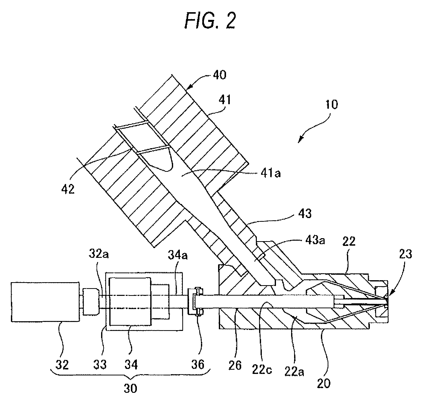
[0027]FIG. 2 is an explanatory diagram which explains a hose extrusion apparatus 10 for extruding a hose H. The hose extrusion apparatus 10 includes a hose extrusion unit 20, a die position control mechanism 30 adapted to be driven to change a bent configuration of an extruded tubular member HA which is extruded from the hose extrusion unit 20, and a rubber extrusion unit 40 for supplying a rubb...


PUM

PropertyMeasurementUnit
Velocityaaaaaaaaaa

Abstract

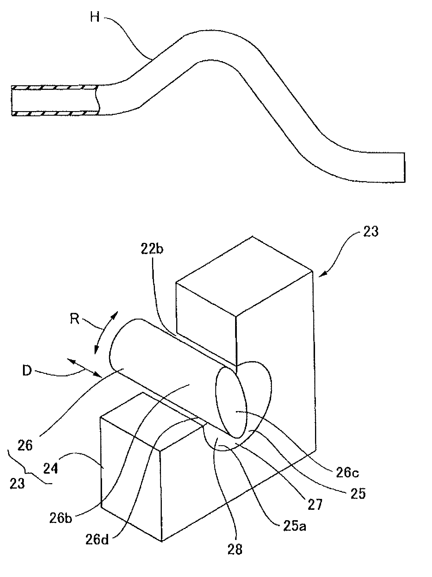
According to a fabrication method, an extruded tubular member HA is formed, using an extrusion die 23 which has an extrusion orifice 25 having an opening-side inner circumferential surface 25a having a circular section and a core-side die 26 disposed concentrically with the extrusion orifice 25, by extruding a tube material through an extrusion passage 27 defined between the opening-side inner circumferential surface 25 and a core-side outer circumferential surface 26d of the core-side die 26. As this occurs, a bent configuration is given to the extruded tubular member HA by changing contact areas where the tube material contacts the opening-side inner circumferential surface 25a and the core-side outer circumferential surface 26d in a circumferential direction so as to set velocities at which the tube material is extruded to different values in the circumferential direction by controlling the position of the core die 26 in rotating and axial directions relative to the extrusion orifice 25.

Description

BACKGROUND OF THE INVENTION[0001]1. Field of the Invention[0002]The present invention relates to a method for fabricating a bent tubular member for use in a hot water line or a fuel line of a motor vehicle or other machines and a tubular member extrusion apparatus.[0003]2. Description of the Related Art[0004]A conventional hose fabrication method for fabricating the type of bent hose described above comprises the following steps. Namely, a hose intermediate is formed by extruding an un-vulcanized rubber. The hose intermediate formed is then cooled and is cut to a predetermined length after a parting agent has been applied thereto. Further, the hose intermediate is manually placed on a metallic mandrel having a bent shape for vulcanization so as to form a hose. Furthermore, the hose is manually removed from the mandrel. In the steps in which the metallic mandrel is used, since the placement of the hose intermediate on the mandrel and removal of the vulcanized hose from the mandrel ar...

Claims


Application Information

Patent Timeline
IPC IPC(8): B29C53/08B29C47/22B29C47/24B29C48/09B29C48/325B29C48/33B29C48/34B29K21/00B29L23/00
CPCB29C47/28B29C47/24B29C47/0023B29C47/0026B29C47/0038B29K2021/00B29L2023/005B29C48/34B29C48/33B29C48/001B29C48/09B29C48/10
Inventor KIMURA, YOJISATO, KYOHEIYAMAGUCHI, HIROSHIMIURA, YUKIO
Owner TOYODA GOSEI CO LTD
Learn More