
Developer accommodating container, process cartridge and electrophotographic image forming apparatus

a technology of electrophotographic image and container, applied in the direction of electrographic process apparatus, optics, instruments, etc., can solve problems such as loss of synchronization, and achieve the effects of reducing the degree of increasing the strength of the flexible container, and reducing the flexure of the flexible container

Inactive Publication Date: 2015-02-17
CANON KK
View PDF4 Cites 2 Cited by
  • Summary
  • Abstract
  • Description
  • Claims
  • Application Information

AI Technical Summary

Benefits of technology

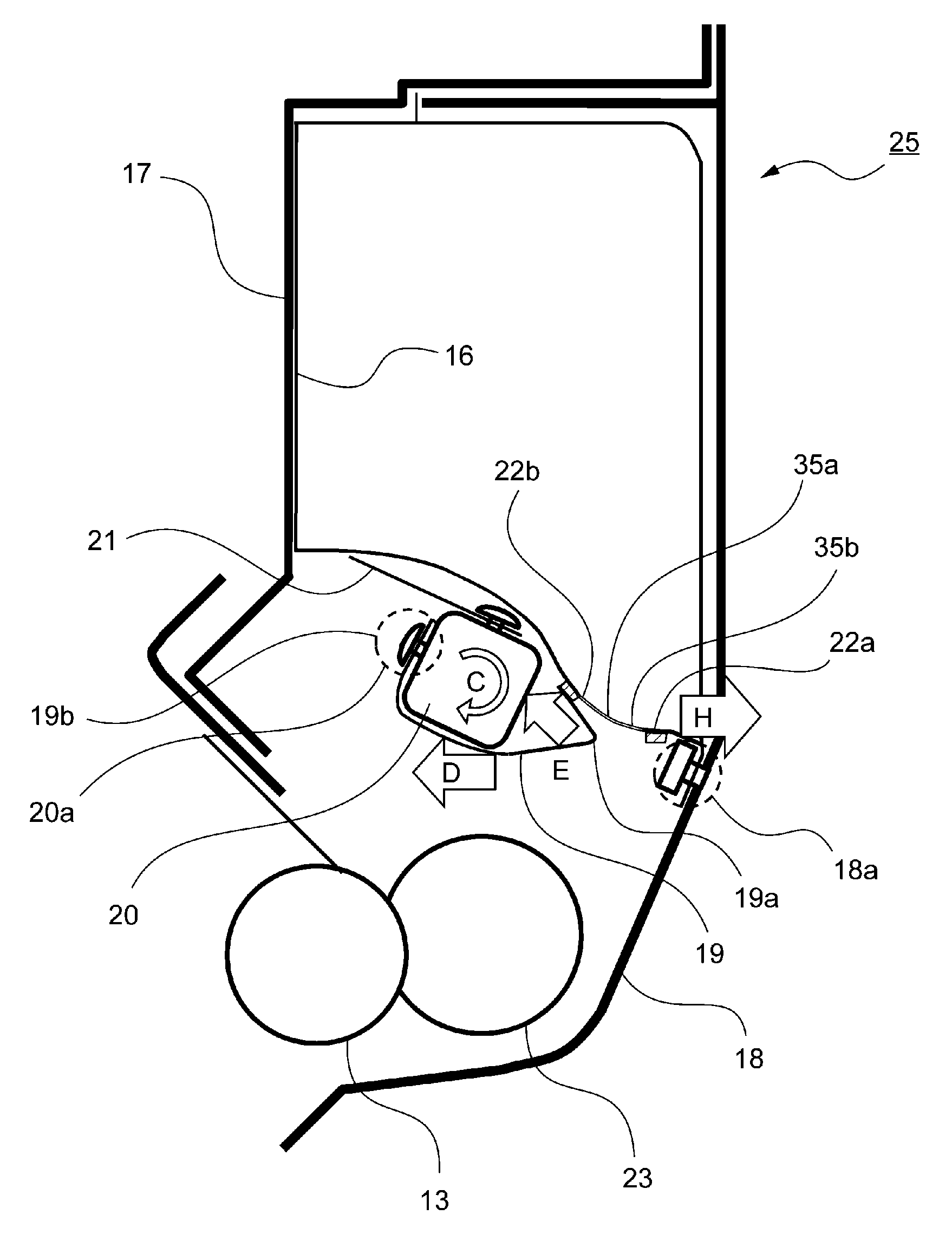
[0010]A principal object of the present invention is to provide a developer accommodating unit capable of increasing strength of a flexible container at a portion, where powder pressure of a developer is applied, to reduce a degree of flexure of the flexible container and thus capable of compatibly realizing downsizing of a developing device and improvement in efficiency of discharge of the developer from the flexible container.

Problems solved by technology

For that reason, there was a possibility that an excessive torque was generated in the rotatable member and thus a stopping motor of the image forming apparatus caused loss of synchronism.

Method used


Image

  • Developer accommodating container, process cartridge and electrophotographic image forming apparatus
  • Developer accommodating container, process cartridge and electrophotographic image forming apparatus
  • Developer accommodating container, process cartridge and electrophotographic image forming apparatus

Examples


embodiment 1

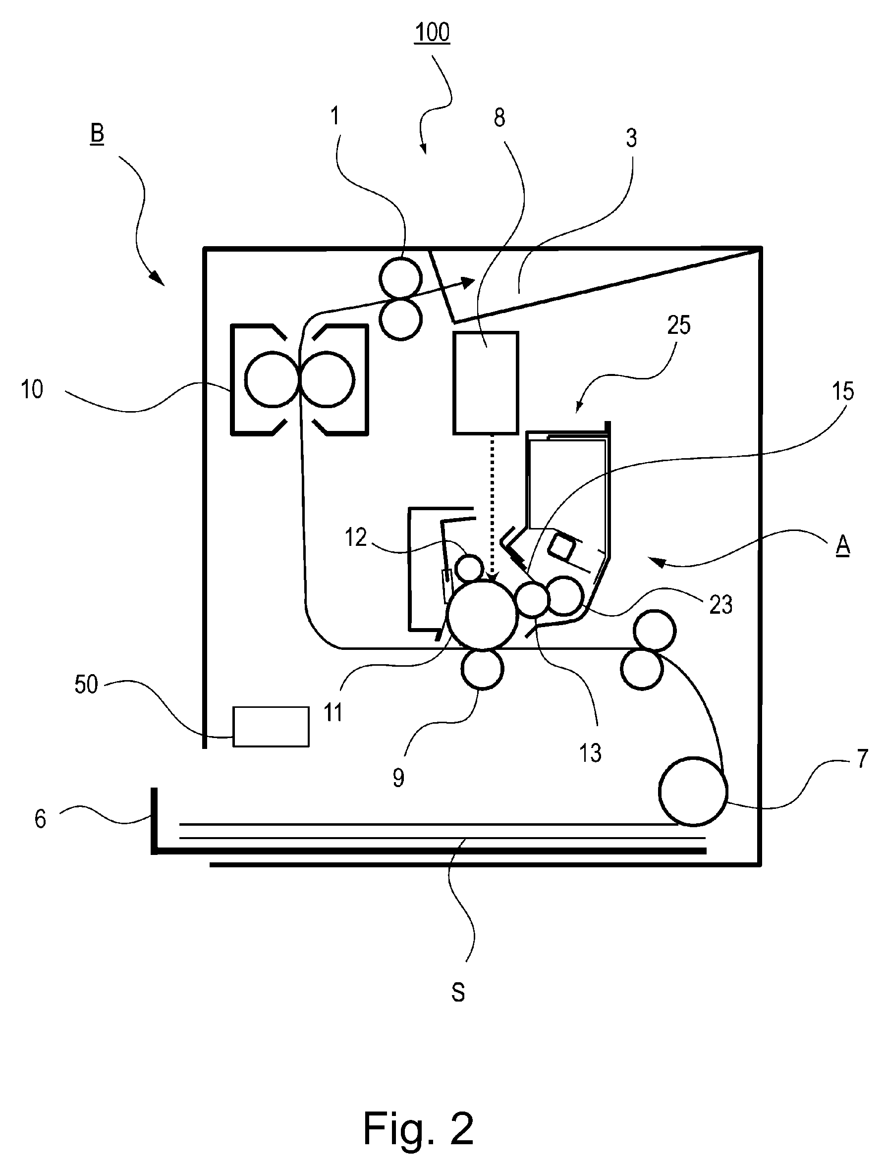
[0039]FIG. 2 is a sectional view showing a structure of an image forming apparatus 100. As shown in FIG. 2, the image forming apparatus 100 as an electrophotographic image forming apparatus includes an apparatus main assembly B as an image forming apparatus main assembly and is constituted so that a cartridge A as a process cartridge is detachably mountable to the apparatus main assembly B. The cartridge A is prepared by integrally assembling a photosensitive drum 1 and a developer accommodating unit 25. In a sheet cassette 6 mounted to a lower portion of the apparatus main assembly B, sheets S are accommodated. During image formation, the sheet S is fed toward the photosensitive drum 11, as an electrophotographic photosensitive drum which is an image bearing member, by a feeding roller 7.

[0040]In synchronism with this operation, the surface of the photosensitive drum 11 is electrically charged uniformly by a charging roller 12 and exposed to light by an exposure device 8, so that a...

embodiment 2

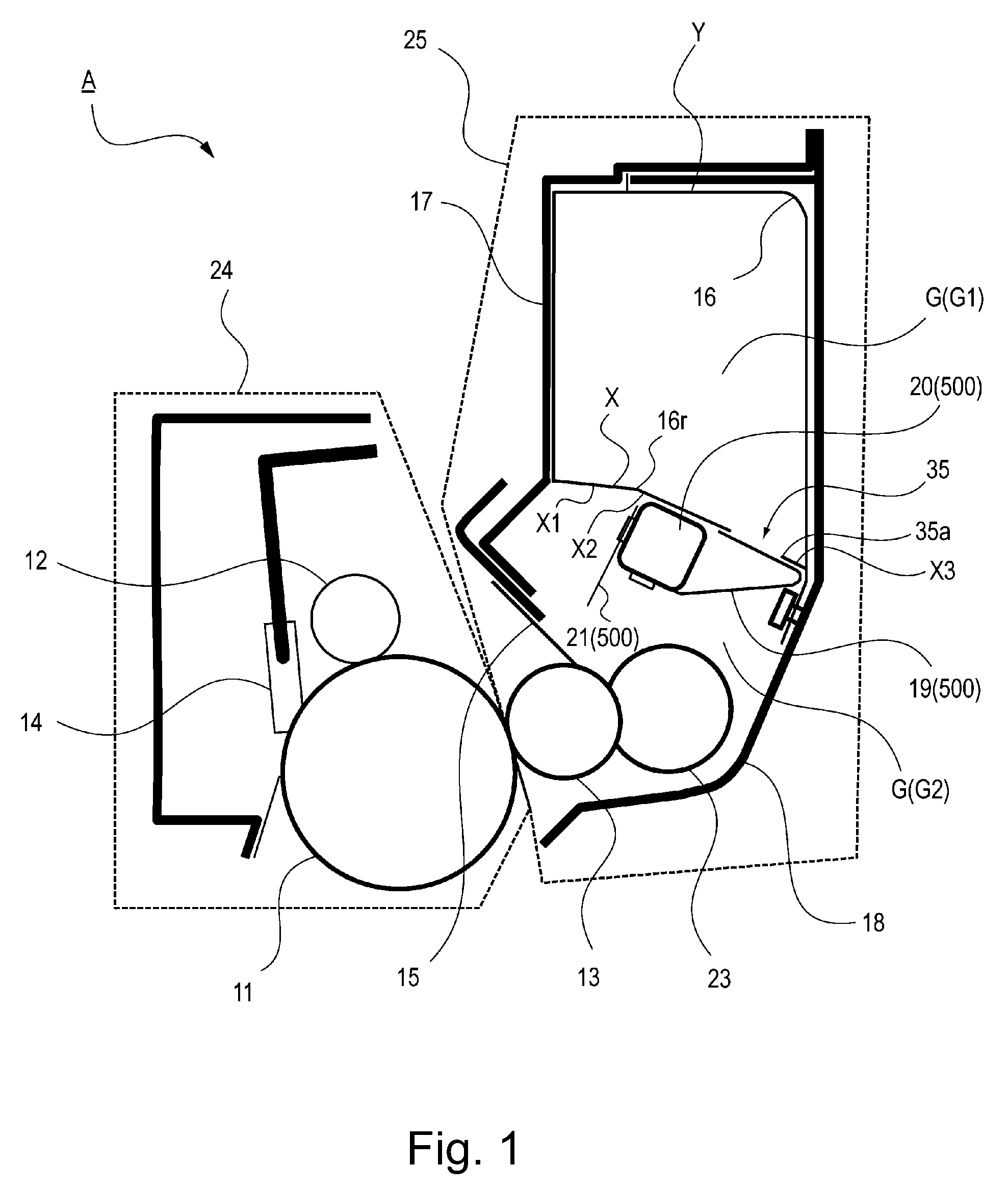
[0205]Parts (a) to (c) of FIG. 19 are sectional views for illustrating a structure of a developer accommodating unit 25 in this embodiment. Constituent elements (members), of the developer accommodating unit 25 in this embodiment, having the same constitutions and effects as those of the developer accommodating unit 25 in Embodiment 1 are represented by the same reference numerals or symbols and will be appropriately omitted from description. Also in this embodiment, the developer accommodating unit 25 can be applied to the image forming apparatus similar to that in Embodiment 1, and therefore the explanation of the image forming apparatus will be omitted. The developer accommodating unit 25 in this embodiment is characterized in that the side on which the self-weight of the developer is exerted is not limited to the lower side with respect to the vertical direction. That is, in Embodiment 1, the self-weight of the developer is exerted toward the lower side with respect to the verti...


PUM


Abstract

A developer accommodating unit includes: a flexible container, provided with an opening for permitting discharge of a developer, for accommodating the developer; a frame for accommodating the flexible container and for accommodating the developer discharged from the flexible container; and an urging member, provided inside the frame, for urging the flexible container to deform the flexible container. The flexible container has a plurality of sides, where the developer accommodated inside the flexible container receives gravitation, defined by a bent portion. The sides are capable of receiving an urging force of the urging member.

Description

FIELD OF THE INVENTION AND RELATED ART[0001]The present invention relates to a developer accommodating unit for use with an image forming apparatus, a process cartridge including the developer accommodating unit, and an electrophotographic image forming apparatus in which these members are incorporated.[0002]The image forming apparatus forms an image on a recording material (medium) by using, e.g., an electrophotographic image forming process and may include, e.g., an electrophotographic copying machine, an electrophotographic printer (such as an LED printer or a laser beam printer), an electrophotographic facsimile machine, and the like.[0003]Further, the process cartridge refers to a cartridge, prepared by integrally assembling at least a developing means and a developing device, detachably mountable to a main assembly of the image forming apparatus and refers to a cartridge, prepared by integrally assembling the developing device and a photosensitive member unit including at leas...

Claims


Application Information

Patent Timeline
Patent Type & Authority Patents(United States)
IPC IPC(8): G03G15/08
CPCG03G15/0896G03G15/0874
Inventor MATSUNAGA, TOMONORISHINDO, GO
Owner CANON KK
Learn More