
Power add-on device for manual wheelchair

a technology of add-on devices and manual wheelchairs, which is applied in the direction of wheelchairs/patients, bicycles, tractors, etc., can solve the problems of inability to easily attach/detach power add-on devices to manual wheelchairs, high cost, and cumbersomeness of electric-powered wheelchairs, and achieve the effect of reducing tipping

Active Publication Date: 2015-02-24
TALLINO PATRICK
View PDF23 Cites 10 Cited by
  • Summary
  • Abstract
  • Description
  • Claims
  • Application Information

AI Technical Summary

Benefits of technology

The present invention is a power add-on device for wheelchairs that can be easily attached and detached from the wheelchair. It features front and back anti-tip castor wheels to reduce tipping and can be lifted several inches off the ground when encountering obstacles or by the user leaning back. The latching mechanism is not tightly clamped down on the camber tube, allowing the camber tube to rotate slightly as the wheelchair tilts. This allows the front wheels of the manual wheelchair to be lifted. The power add-on device can be detached from the wheelchair and loaded into the trunk of a car or checked in as baggage when flying.

Problems solved by technology

However, lengthy outings or ones that require traversing uneven or sloped terrain are unrealistic and often impossible for many using manual chairs.
Although electric-powered wheelchairs exist that can be used for those situations, they are not generally prescribed unless the user lacks the ability to use a manual wheelchair.
Moreover, electric-powered wheelchairs tend to be expensive, heavy, and cumbersome.
Although such devices are somewhat useful and beneficial, the existing technology fails to provide an easy way to attach / detach a power add-on device to a conventional manual wheelchair.
Furthermore, such devices fail to provide for traversal over rough terrain and adequate stability.
Additionally, many such devices require modification to the manual wheelchair.

Method used


Image

  • Power add-on device for manual wheelchair
  • Power add-on device for manual wheelchair
  • Power add-on device for manual wheelchair

Examples


Embodiment Construction

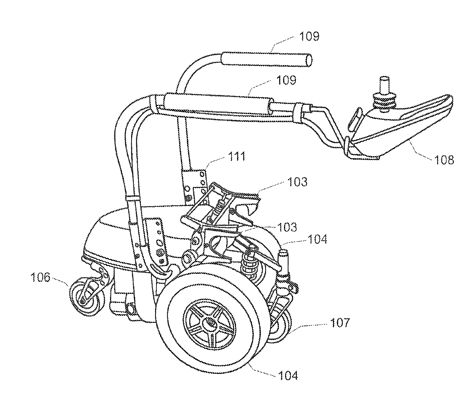
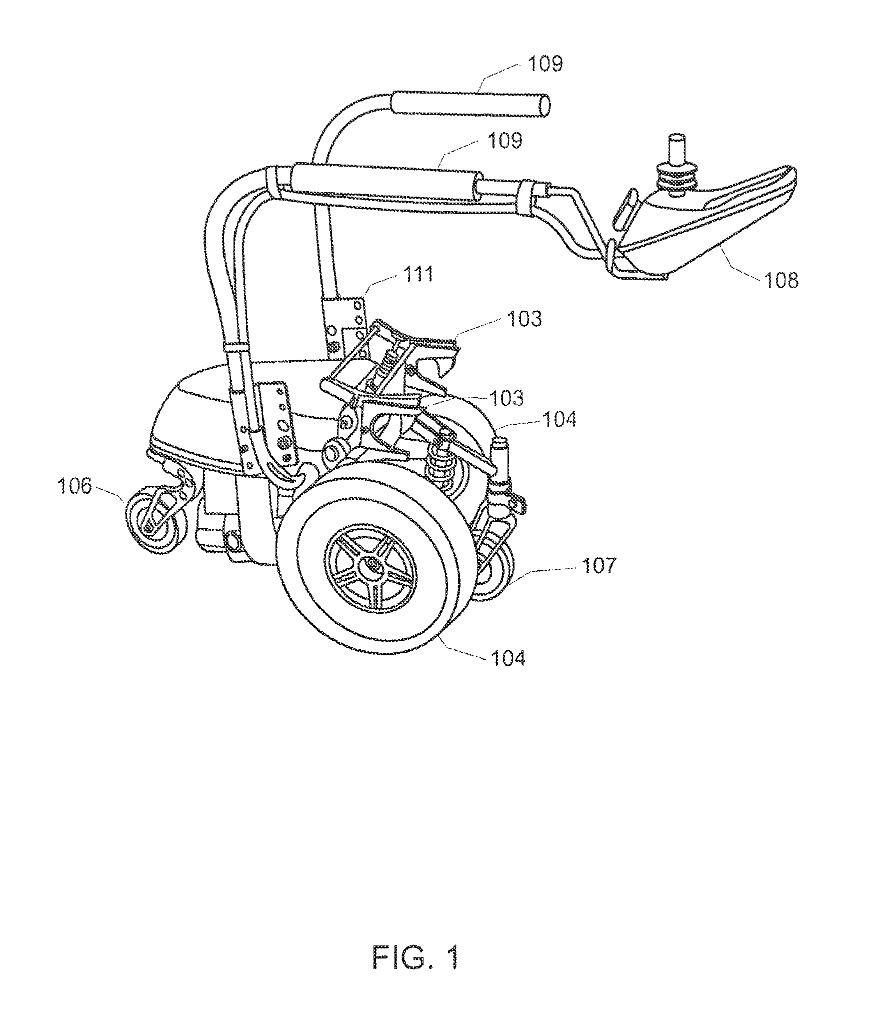
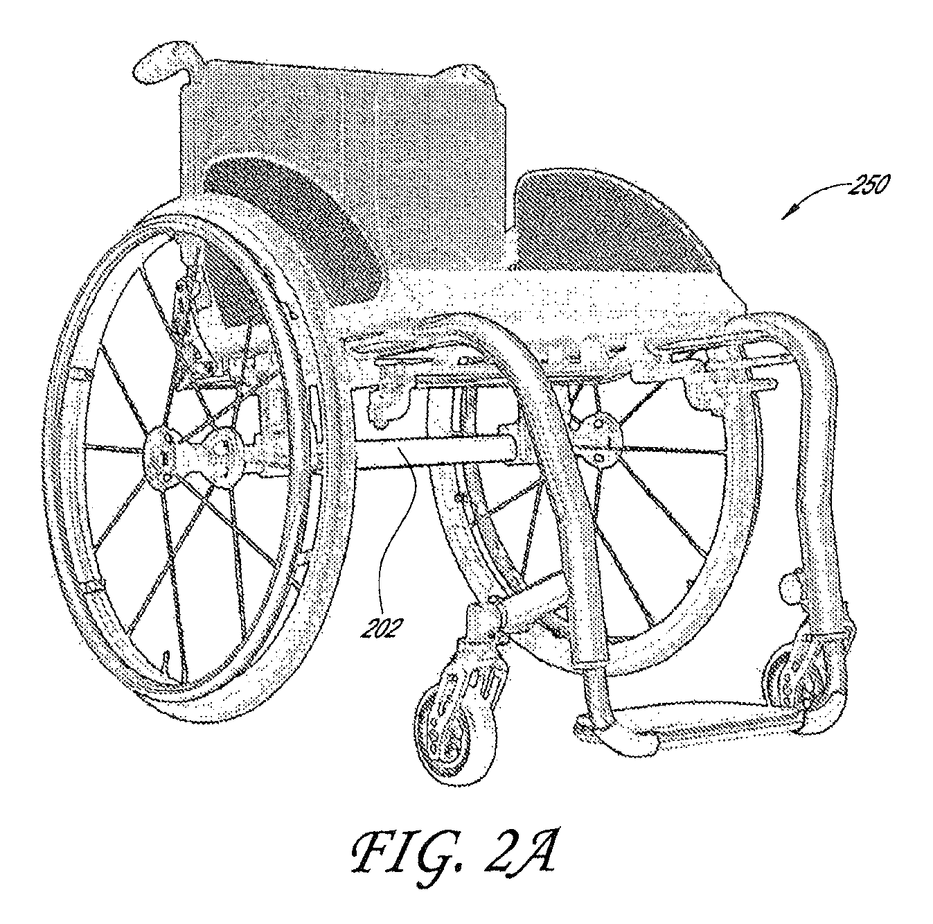
[0031]FIG. 1 illustrates an exemplary power add-on device 100 useable for powering a manual wheelchair, in accordance with a preferred embodiment of the present invention. FIG. 2B illustrates the power add-on device 100 attached to a manual wheelchair 201 having a camber tube 202. The power add-on device 100 includes a housing 102. The housing 102 includes, therein, two conventional electric wheel-chair motors that are electrically coupled to a power source, and are arranged so that each drives a wheel 104. The manual wheelchair 201 can be attached to the power add-on device 100 simply by backing up the manual wheelchair 201 until a pair of latches 103 holds the camber tube of the manual wheelchair 201. Advantageously, no modification is required to the manual wheelchair 201.

[0032]Preferably, the latches 103 can be activated by an electric actuator so that when a user wants to de-couple the power add-on device 100 from the manual wheelchair 250, the user employs remote control 108 t...


PUM


Abstract

A power add-on device for powering a manual wheelchair includes a motorized component including dual electric motors and a power source electrically coupled to the electric motors, wherein each of the motors is configured to turn a respective one of a set of drive wheels. The power add-on device includes a latching mechanism adapted to attach the power add-on device to the camber tube of the manual wheelchair; and a controller, reachable by a person sitting in the manual wheelchair, that controls the latching mechanism, the motors, and a swing arm that allows the rear wheels of the manual wheelchair to be lifted off the ground. The front wheels of the manual wheelchair are allowed to be lifted several inches off the ground to avoid obstacles, or can be lifted by the user leaning back. Advantageously, the power add-on device can be detached from the manual wheelchair and loaded into the trunk of a car when travelling or may be checked in as baggage when flying.

Description

CROSS-REFERENCE TO RELATED APPLICATIONS[0001]This application is a continuation-in-part of U.S. patent application Ser. No. 12 / 788,147, filed on May 26, 2010 (entitled “Power Add-On Device For Manual Wheelchair”), which claims the benefit under 35 U.S.C. §119 of U.S. Provisional Patent Application No. 61 / 181,602 filed by Patrick Tallino on May 27, 2009 and entitled “Power Add-On Device For Manual Wheelchair”, the entirety of each of which is hereby incorporated by reference as if fully set forth herein.BACKGROUND OF THE INVENTION[0002]1. Field of the Invention[0003]The present invention relates to an auxiliary power add-on attachment for a manual rigid-framed wheelchair.[0004]2. Description of the Related Art[0005]Most spinal cord-injured individuals with injury levels from the five cervical vertebrate down to the lumbar vertebrates use a lightweight rigid framed manual wheelchair for everyday use. However, lengthy outings or ones that require traversing uneven or sloped terrain are...

Claims


Application Information

Patent Timeline
Patent Type & Authority Patents(United States)
IPC IPC(8): A61G5/04A61G5/10B62B5/00
CPCA61G5/04A61G5/047B62B5/0079A61G5/043A61G2203/14A61G2005/1054A61G5/1054
Inventor TALLINO, PATRICK
Owner TALLINO PATRICK
Learn More