LED housing

a technology for led lighting and housing, which is applied in the direction of semiconductor devices for light sources, lighting and heating apparatus, and light support devices, etc., can solve the problems of undesirable effects of rapid temperature fluctuations, and achieve the effect of efficient aiding in mounting the housing

Inactive Publication Date: 2015-02-24
GENERAL LED AI HLDG LLC
View PDF2 Cites 0 Cited by
  • Summary
  • Abstract
  • Description
  • Claims
  • Application Information

AI Technical Summary

Benefits of technology

[0010]The housing will have electrical conduits that run through the housing to each LED chip contained therein. The electrical conduits will be advantageously placed on the outside of the housing to efficiently aid in mounting the housing on a PCB substrate. The electrical conduits will be situated such that all positive conduits will be on the same side as each other while the negative conduits will be on the same side as each other.
[0011]The housing will also have a heat sink feature built into the housing that will aid in controlling the temperature of the LED chips. The heat sink feature will be a metallic / copper plate that is closely situated to the LED chips. The copper plate is situated near to all three chips such that the same plating can be used to maintain the temperature of the chips at the same time.

Problems solved by technology

Rapid fluctuations in the temperature can have undesirable effects in an LED lighting as the color and the luminance of light emitted by the LED will also vary greatly with the temperature fluctuations and will be noticed in a lighting fixture that uses LEDs.

Method used


Image

  • LED housing
  • LED housing
  • LED housing

Examples


Embodiment Construction

[0019]For the purposes of understanding the invention, reference will now be made to the embodiments illustrated in the drawings. It will be understood that no limitation of the scope of the invention is thereby intended. Any alterations and further modifications in the described embodiments, and any further applications of the principles of the invention as described herein are contemplated as would normally occur to one skilled in the art to which the invention relates.

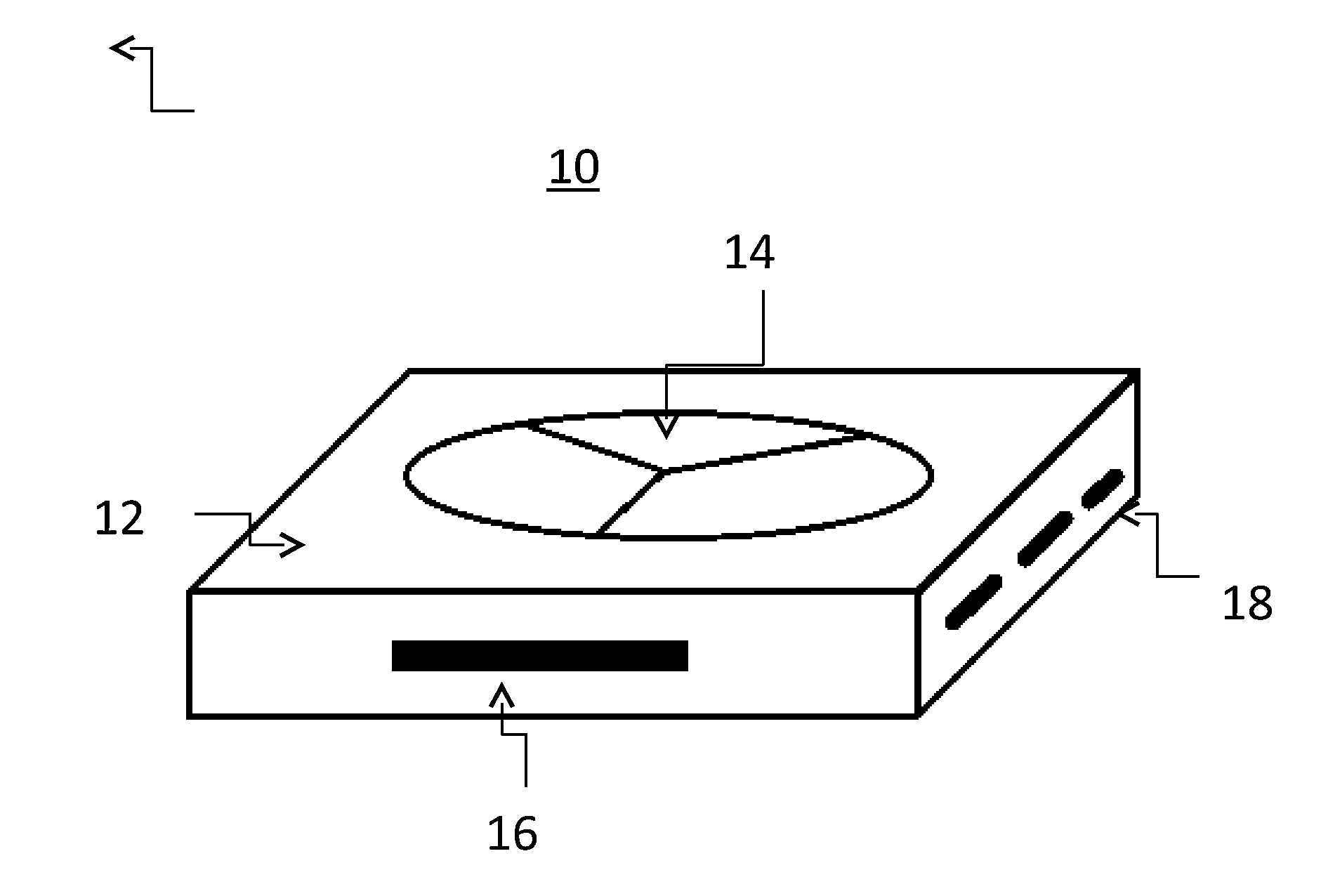
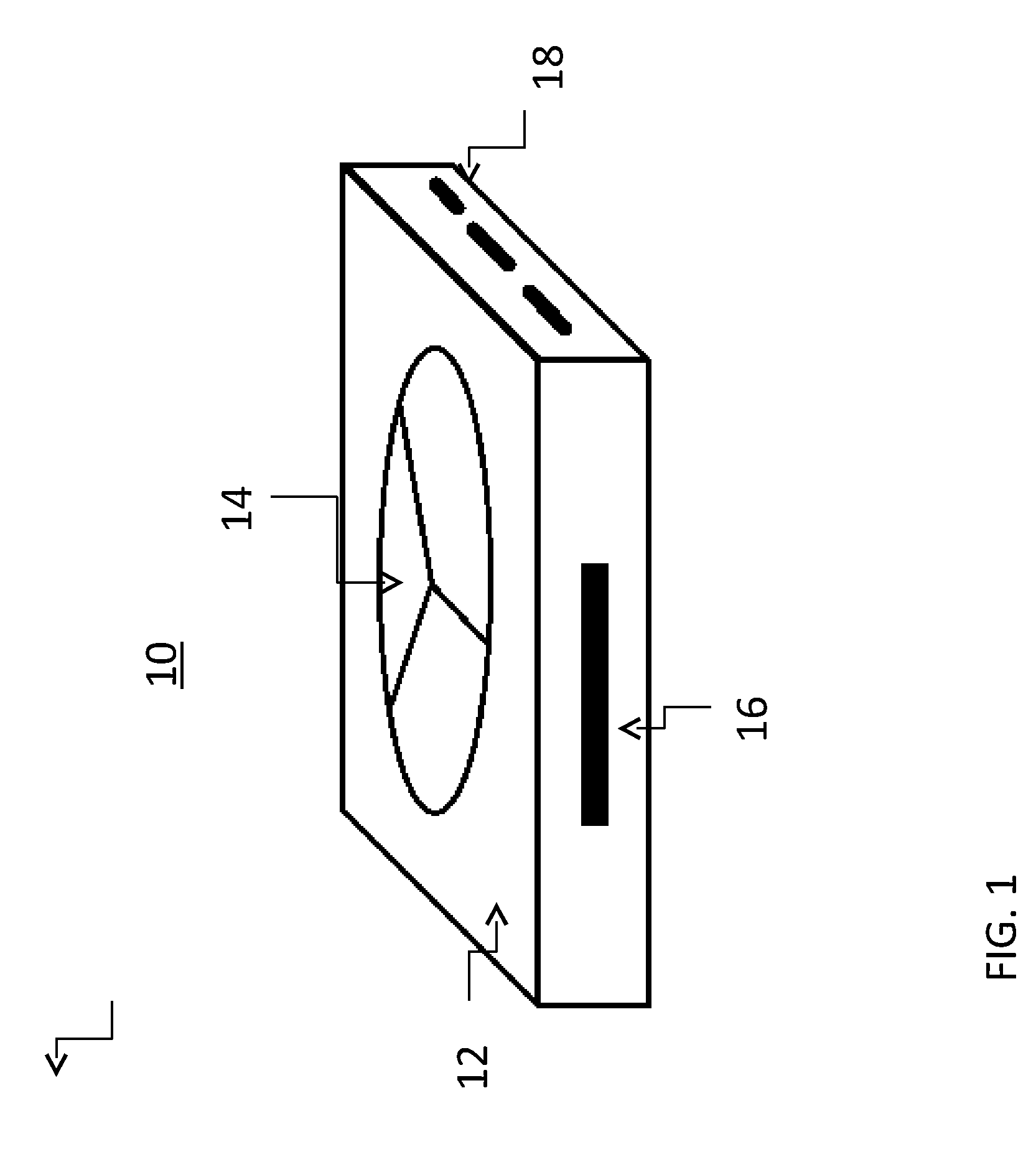
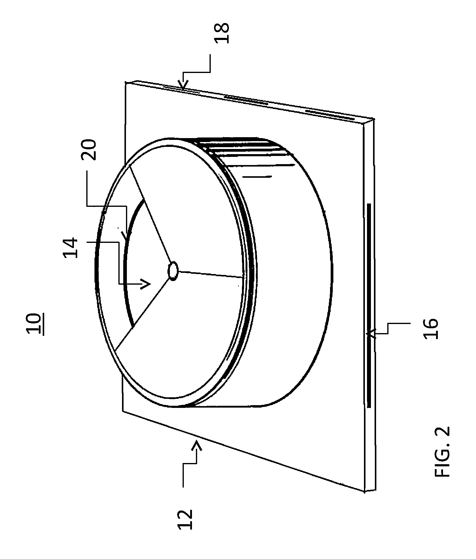
[0020]Referring to FIG. 1, one embodiment of the invented LED housing is depicted. Housing 10 is composed of mounting section 12 and chamber section 14. Chamber section 14 is composed of a cylindrical hole that is in the center of housing 10. Chamber section 14 is composed of three separate chambers. Each chamber has walls that divide each chamber. These walls are rigid walls and are capable of containing a liquid within the chamber and keeping it separate from the other chambers. This allows several different color...


PUM


Abstract

An LED housing unit is described wherein the housing unit will have a chambered section connected to a mounting section. The mounting section will be mountable onto a base, such as a PCB mounting in a light fixture. The chambered section will have a plurality of chambers that have separating walls and each chamber will be able to hold an LED chip and liquid. The housing unit will also have a heat sink within the housing that extends outside of the housing. Electrical conduits will lead to the LED chips within each chamber and will lead to locations outside of the housing. All the positive leads will lead to one side of the housing while the negative leads will lead to the other side of the housing.

Description

CROSS-REFERENCE TO RELATED APPLICATIONS[0001]This application relates to and claims priority rights from provisional applications U.S. 61 / 758674 and U.S. 61 / 692856 filed on Jan. 30, 2013 and Aug. 24, 2012, the entire disclosures of which are hereby incorporated by reference herein.BACKGROUND OF THE INVENTION[0002]1. Field of the Invention[0003]This invention relates to a housing for an LED lighting device.[0004]2. Description of the Related Art[0005]LEDs are rapidly becoming a popular source of lighting systems. Using LEDs provide numerous advantages over traditional light bulbs. For example, the size of the LED is dramatically smaller than a typical incandescent bulb, but the luminance of the LED can be just as strong or even greater. Since an LED is a relatively small semiconductor device, lighting fixtures employing these devices will try to optimize the light provided and minimize the space requirements and costs of the device.[0006]LED lighting fixtures have been capable of pro...

Claims


Application Information

Patent Timeline
Patent Type & Authority Patents(United States)
IPC IPC(8): F21V9/16F21V29/00
CPCF21V29/22F21V29/70F21K9/62F21K9/64F21Y2115/10
Inventor GUERRIERI, SALVATORE
Owner GENERAL LED AI HLDG LLC
Why Eureka
Try Eureka