Eureka AIR delivers breakthrough ideas for toughest innovation challenges, trusted by R&D personnel around the world.

Receiver

a technology of receiver and resistor, which is applied in the field of receiver, can solve the problem of difficult to realize the termination impedance matching resistor r with a resistance capable of accurately, and achieve the effect of enhancing the accuracy of signal reception

Active Publication Date: 2015-02-24
NOVATEK MICROELECTRONICS CORP
View PDF7 Cites 4 Cited by
  • Summary
  • Abstract
  • Description
  • Claims
  • Application Information

AI Technical Summary

Benefits of technology

[0007]It is therefore an objective of the present invention to provide a receiver capable of adjusting termination resistance for performing impedance matching according to a received external calibration signal to enhance accuracy of signal reception.
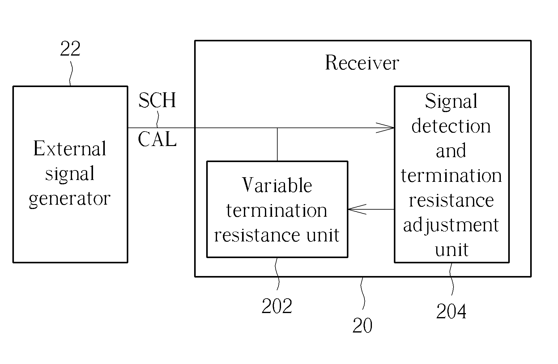
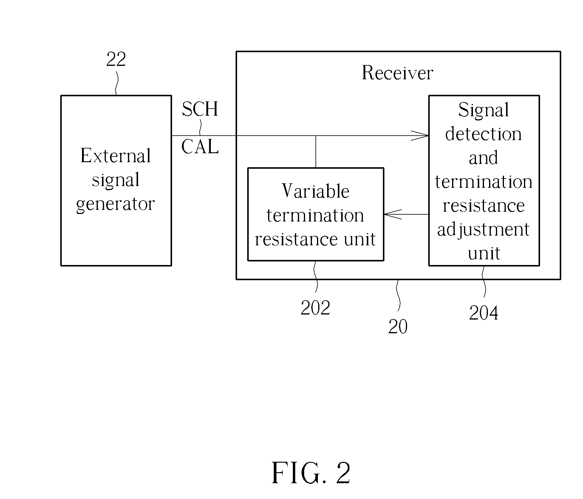
[0008]The present invention discloses a receiver, capable of enhancing accuracy of signal reception. The receiver comprises a variable termination resistance unit, coupled to at least one channel, for utilizing at least one termination resistance corresponding to the at least one channel to perform impedance matching, and a signal detection and termination resistance adjustment unit, for detecting at least one external calibration signal corresponding to the at least one channel from at least one external signal generator, and adjusting the at least one termination resistance.

Problems solved by technology

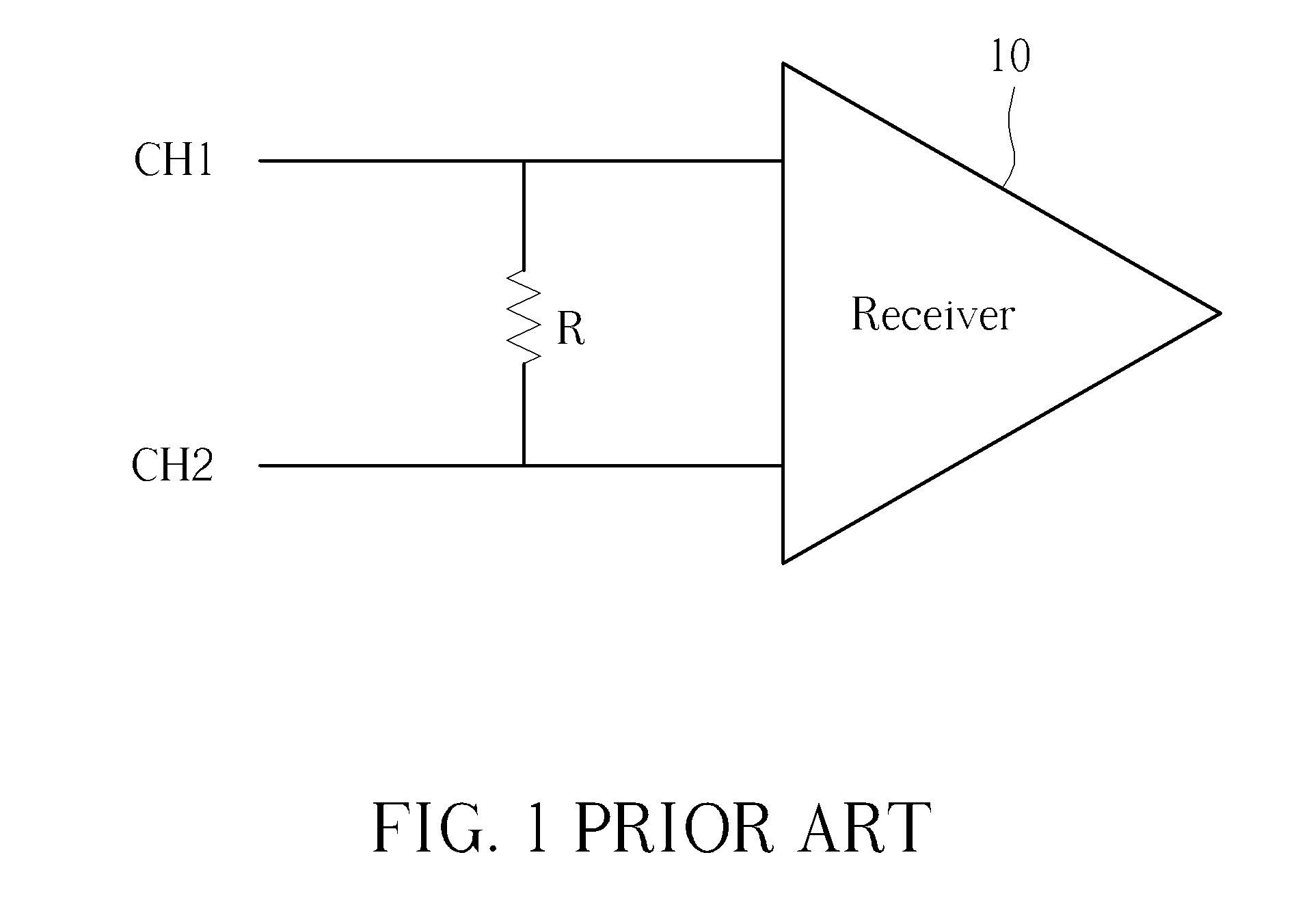
Therefore, it is hard to realize the termination impedance matching resistor R with a resistance capable of accurately matching with termination resistance of transmitter.

Method used


Image

  • Receiver
  • Receiver
  • Receiver

Examples


Embodiment Construction

[0015]Please refer to FIG. 2, which is a schematic diagram of a receiver 20 according to an embodiment of the invention. As shown in FIG. 2, the receiver 20 is coupled to an external signal generator 22 through a channel SCH, and includes a variable termination resistance unit 202 and a signal detection and termination resistance adjustment unit 204. In short, when the receiver 20 intends to receive signals from the external signal generator 22 through the channel SCH, the receiver 20 first receives an external calibration signal CAL from the external signal generator 22 to perform calibration. At this moment, the variable termination resistance unit 202 coupled to the channel SCH utilizes a current termination resistance corresponding to the channel SCH to perform impedance matching first. Then, the signal detection and termination resistance adjustment unit 204 detects the received external calibration signal CAL based on the current termination resistance corresponding to the cha...


PUM


Abstract

The present invention discloses a receiver capable of enhancing accuracy of signal reception. The receiver includes a variable termination resistance unit, coupled to at least one channel, for utilizing at least one termination resistance corresponding to the at least one channel to perform impedance matching, and a signal detection and termination resistance adjustment unit, for detecting at least one external calibration signal corresponding to the at least one channel from at least one external signal generator, and adjusting the at least one termination resistance.

Description

BACKGROUND OF THE INVENTION[0001]1. Field of the Invention[0002]The present invention relates to a receiver, and more particularly, to a receiver capable of adjusting termination resistance for performing calibration according to a received external calibration signal to enhance accuracy of signal reception.[0003]2. Description of the Prior Art[0004]In general, a termination impedance matching resistor is required in an interface circuit receiver to maintain completeness of a received signal, i.e. when a termination impedance matching resistance of the receiver accurately matches a termination resistance of the transmitter, the accuracy of signal reception can be enhanced.[0005]Please refer to FIG. 1, which illustrates a schematic diagram of a conventional interface circuit receiver 10. As shown in FIG. 1, in many applications, when the interface circuit receiver 10 receives differential signals from a transmitter through channels CH1 and CH2, a termination impedance matching resist...

Claims


Application Information

Patent Timeline
Patent Type & Authority Patents(United States)
IPC IPC(8): H03K17/16H04L25/02H04L25/12
CPCH04L25/12H04L25/0278H04L25/0292
Inventor WU, TSE-HUNG
Owner NOVATEK MICROELECTRONICS CORP
Why Eureka
Eureka Blog
Learn More