Acoustic igniter

Active Publication Date: 2015-03-03
SIERRA SPACE CORP
View PDF18 Cites 24 Cited by
  • Summary
  • Abstract
  • Description
  • Claims
  • Application Information

AI Technical Summary

Benefits of technology

[0008]The acoustic resonance igniter of the present invention employs pressurized gas supplied to a manifold which exits through a nozzle to form a sonic or under-expanded supersonic jet. This pressurized gas is known as the driver gas. An essentially blind resonance cavity in an axially extending central body has an open end which is spaced from the nozzle in an ignition chamber and is positioned to receive the under-expanded jet. The jet of driver gas sets up a high-frequency sonic resonance which heats a small quantity of the gas within the resonance cavity through periodic shock waves that propagate the length of the cavity, reflect off of the closed cavity wall, and travel back towards the mouth of the cavity. The temperature of this gas can exceed 1200 Kelvin. A secondary propellant injector pintle extends through the driver gas manifold along the axis of the nozzle

Problems solved by technology

Ignition is particularly a concern in liquid rocket engines where both the fuel and oxidizer are supplied as liquids to the chamber, because any momentary delay in ignition can result in the accumulation of an explosive mixture of fuel and oxidizer, resulting in a hard start which may damage or destroy the engine.
Reusable engines also require multiple starts, and, while replaceable pyrotechnic igniters are possible, they may leave residues which may add to the cost of reconditioning the engine for re-flight.
In such a case multiple starts becomes complicated.
Although engines utilizing hypergolic propellants readily perform multiple restarts a

Method used


Image

  • Acoustic igniter
  • Acoustic igniter
  • Acoustic igniter

Examples


Embodiment Construction

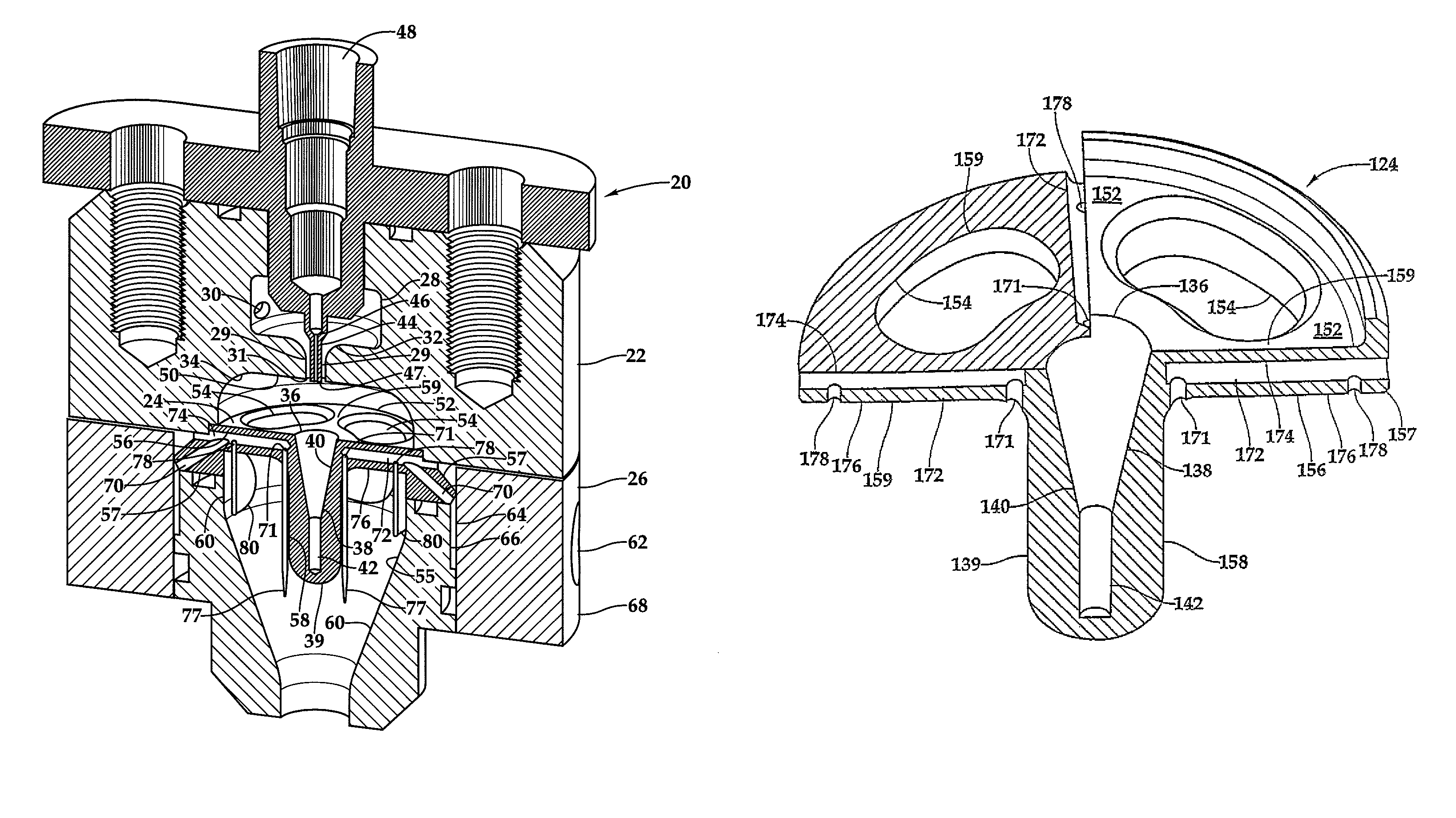
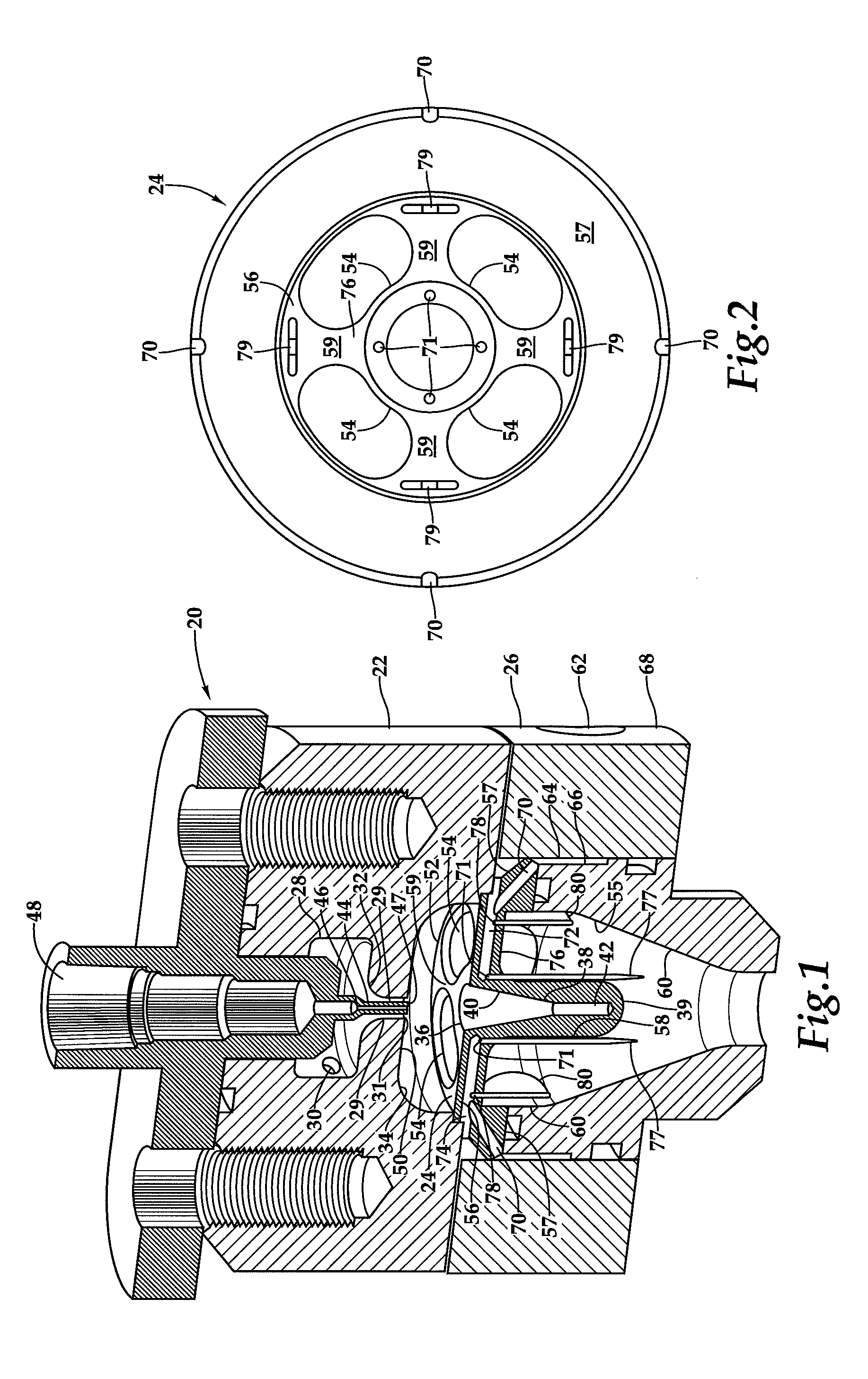
[0021]Referring more particularly to FIGS. 1-5 wherein like numbers refer to similar parts, an acoustical resonance igniter 20 is best shown in FIG. 1. The acoustic igniter 20 comprises three parts: an injector subassembly 22, a resonator subassembly 24, and a combustion chamber subassembly 26. The ignition subassembly 22 comprises an oxygen manifold 28 connected to a source 30 of high-pressure oxygen gas. The oxygen manifold 28 leads to a converging nozzle 32 which empties into an ignition chamber 34 formed between the injector subassembly 22 and the resonator subassembly 24. The high-pressure (e.g., 30-1200 psi) oxygen source 30 supplies gaseous oxygen to the oxygen manifold 28 where the gaseous oxygen is accelerated through a sonic nozzle 29. The sonic nozzle 29 has a nozzle outlet 31 from which an under-expanded jet of sonic or supersonic gas is expelled. The under-expanded jet is directed toward an opening 36 which leads into a resonance cavity 38 formed by axially extending ce...


PUM


Abstract

An acoustic resonance igniter uses gas expanding through a nozzle to form a sonic, or under-expanded supersonic, jet directed against the opening of a blind resonance cavity in a central body, setting up a high-frequency sonic resonance which heats the gas within the cavity. A pintle extends coaxially with the nozzle and injects liquid propellant into the jet. The liquid propellant ignites with the heated gas within the resonance cavity forming combustion gases. The combustion gases flow through openings in a flange which supports the resonance cavity into a combustion chamber in the same direction as the gas jet flows. The liquid propellant is injected from within the support flange in the direction of combustion gas flow to film cool the combustion chamber wall and the flange and the central body supported by the flange. The acoustic resonance igniter may form a rocket engine ignition torch or a RCS thruster.

Description

STATEMENT AS TO RIGHTS TO INVENTIONS MADE UNDER FEDERALLY SPONSORED RESEARCH AND DEVELOPMENT[0001]This invention was made with government support under contract #FA9300-10-2105 awarded by Air Force Research Laboratory. The government has certain rights in the invention. The government may exercise such rights over assignee's objection in accordance with 35 U.S.C. 202 and 203 if the government finds such action necessary in accord with 35 U.S.C. 203(a)(1-4)CROSS REFERENCES TO RELATED APPLICATIONS[0002]Not applicable.BACKGROUND OF THE INVENTION[0003]The present invention relates to igniters such as used in rocket engines, jet engines and combustors in general, and to igniters utilizing acoustically heated gas as ignition sources in particular.[0004]Generally the safest, most reliable and most widely used method of igniting a combustor which does not employ a pilot light is an electrical spark. This approach is generally reliable and safe, e.g., such as used in an internal combustion e...

Claims


Application Information

Patent Timeline
IPC IPC(8): F02G1/00F02G3/00F02K9/68
CPCF02K9/95F05D2260/99
Inventor MUNSON, SCOTT M.
Owner SIERRA SPACE CORP
Why Eureka
Try Eureka