Brake disc arrangement for disc brakes

a technology of brake discs and brake discs, which is applied in the direction of brake discs, braking systems, transportation and packaging, etc., can solve the problems of preferably radial movement of the connection element relative to the attachment adapter, and achieve the effect of improving the heat balance of the friction ring, preventing the temperature level of the connection element from being higher, and removing heat from all components of the brake disc arrangemen

Inactive Publication Date: 2015-03-03
SAF HOLLAND GMBH
View PDF20 Cites 9 Cited by
  • Summary
  • Abstract
  • Description
  • Claims
  • Application Information

AI Technical Summary

Benefits of technology

[0017]Expediently, the attachment adapter comprises a radial opening which extends from the inner circumference of the attachment adapter to its fastening area, in which the connection element is fastened. Thus, the opening extends essentially along a radial direction or line relative to the axis of rotation of the brake disc arrangement. Here, the opening may have any cross-sectional shape, however, expediently, it is round or circular. Here, the opening may be concentric relative to the hollow space of the connection element. Such an opening expediently improves the heat balance of the friction ring or keeps the temperature level in the connection element lower during the braking process since air may circulate therein.
[0018]Further expediently, the friction ring is designed as an internally ventilated friction ring, wherein preferably the hollow space of the connection element designed as a hollow body communicates with the circulation space of the friction ring. Expediently, an internally ventilated friction ring consists of two ring-shaped discs which are connected by bars such that a circulation space forms between the two discs. This space expediently communicates with the hollow space of the connection element designed as hollow body such that air may flow through the hollow space of the connection element into the circulation space. By this, the removal of heat from all components of the brake disc arrangement is further improved.
[0019]Preferably, the connection element has an anchoring area, preferably provided with recesses or projections, in order to provide for an engagement with the fastening area of the attachment adapter. By this, the stationary connection of the connection element and the attachment adapter is further improved due to the positive locking when the connection element is cast in the attachment adapter or the attachment adapter is cast around the first end of the connection element.

Problems solved by technology

The first end of the connection element is stationarily fixed in the fastening area of the attachment adapter such that—even in the case of great temperature influences—a (preferably radial) movement of the connection element relative to the attachment adapter is not possible.

Method used


Image

  • Brake disc arrangement for disc brakes
  • Brake disc arrangement for disc brakes
  • Brake disc arrangement for disc brakes

Examples


Embodiment Construction

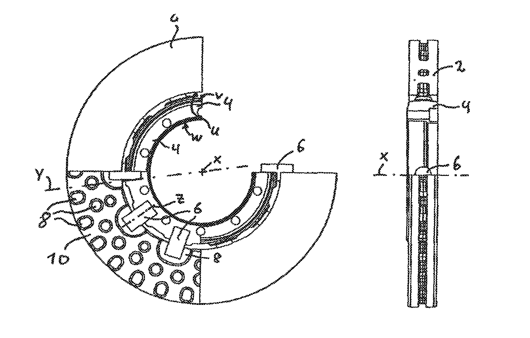
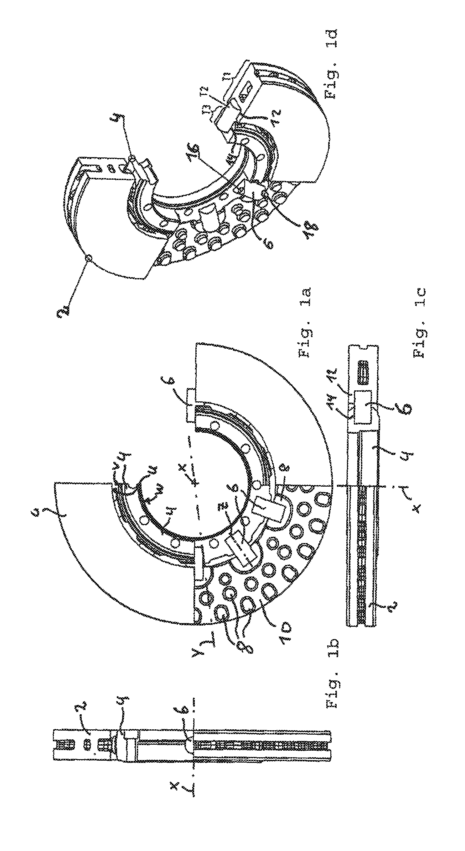
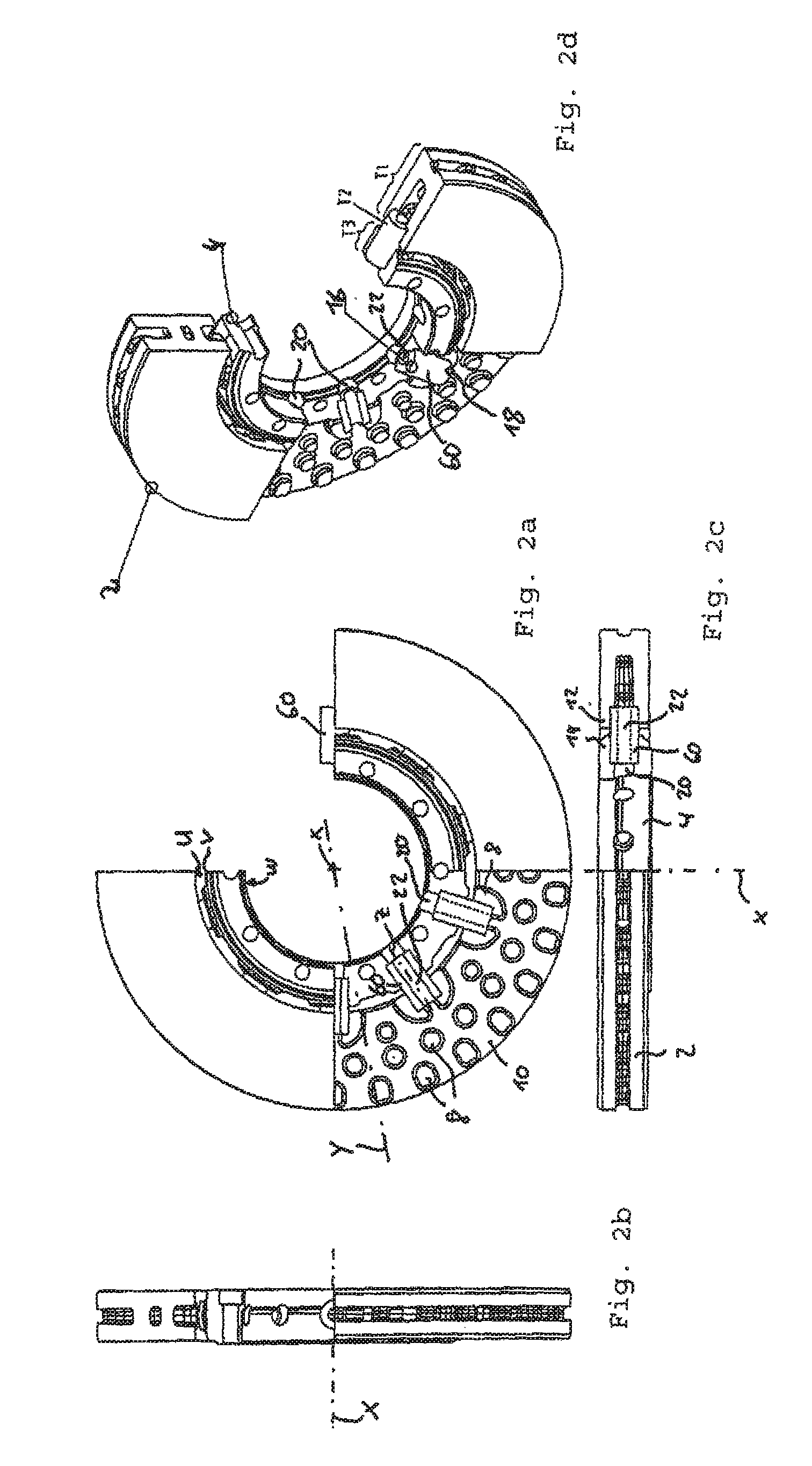
[0063]For purposes of description herein, the terms “upper,”“lower,”“right,”“left,”“rear,”“front,”“vertical,”“horizontal,” and derivatives thereof shall relate to the invention as oriented in FIGS. 1a-1d. However, it is to be understood that the invention may assume various alternative orientations, except where expressly specified to the contrary. It is also to be understood that the specific devices and processes illustrated in the attached drawings, and described in the following specification are simply exemplary embodiments of the inventive concepts defined in the appended claims. Hence, specific dimensions and other characteristics relating to the embodiments disclosed herein are not to be considered as limiting, unless the claims expressly state otherwise.

[0064]The first preferred exemplary embodiment of the brake disc arrangement according to the invention depicted in FIGS. 1a-1d shows a friction ring 2, an attachment adapter 4 as well as a plurality of connection elements 6...


PUM

PropertyMeasurementUnit
areaaaaaaaaaaa
rotationaaaaaaaaaa
forcesaaaaaaaaaa

Abstract

A brake disc arrangement for disc brakes, in particular for land vehicles, including a friction ring, an attachment adapter for attaching the brake disc arrangement to a wheel hub, and at least one connection element for connecting the friction ring and the attachment adapter, wherein the attachment adapter comprises a fastening area in which the connection element is stationarily fixed, and wherein the friction ring comprises a receptacle area in which the connection element is accommodated such that the friction ring can move radially relative to the connection element.

Description

BACKGROUND OF THE INVENTION[0001]The present inventions relates to a brake disc arrangement for disc brakes, for example of land vehicles (such as passenger cars, trucks, commercial vehicles or trailers), as well as a method of manufacturing a brake disc arrangement for disc brakes, also in particular for land vehicles.[0002]Brake disc arrangements of the type in question are known from the prior art. For example, DE 199 29 390 discloses a brake disc arrangement for disc brakes, in which a friction ring is cast onto a toothed adapter so that the brake disc may expand radially and, thus, a ballooning of the disc is avoided, which due to the uneven distribution of stresses might cause the disc to fracture. A problem of such arrangements, however, is that much manufacturing work is necessary since punching burrs have to be removed. Moreover, the known brake disc arrangement is very complex to cast since the brake disc arrangement, due to the different ways of casting its elements, has ...

Claims


Application Information

Patent Timeline
Patent Type & Authority Patents(United States)
IPC IPC(8): F16D65/12F16D65/02
CPCF16D65/123F16D2065/1316F16D2065/1328F16D2065/1344F16D2065/136F16D2250/0007
Inventor DREWES, OLAF
Owner SAF HOLLAND GMBH
Why Eureka
Try Eureka