Micro-power generator for valve control applications

a micro-power generator and valve control technology, applied in the field of valve control, can solve the problems of difficult to build control devices (as well as other types of field devices) with a large amount of functionality, and many field devices don't have the same capabilities that can be found, so as to achieve high reliability and increase the functionality of field devices

Inactive Publication Date: 2015-03-03
WESTLOCK CONTROLS
View PDF18 Cites 21 Cited by
  • Summary
  • Abstract
  • Description
  • Claims
  • Application Information

AI Technical Summary

Benefits of technology

[0006]The disclosed device is a micro-power generator integrated in a pneumatic valve controller, such that the micro-power generator is powered by the same compressed air supply used to operate the valve. The result is a highly reliable source of electric power that can be used to provide increased functionality for field devices used in a variety of applications, including hazardous and classified applications.
[0007]In one embodiment, the micro-power generator includes a micro-turbine connected to a small DC power generator, and a source of compressed air is used to drive the micro-turbine to generate power via the generator. The disclosed arrangement can mitigate some of the aforementioned limitations associated with prior valve control devices.

Problems solved by technology

This presents a challenge because the biggest markets for such automatically-controlled valves are the oil & gas, petrochemical and chemical industries which are often located in hazardous and / or difficult to reach areas.
This imposes severe limitations in the accessibility to the electronic device as well the supply of power to the device.
With a lack of a sufficient power supply, it is difficult to build control devices (as well as other types of field devices) with a large amount of functionality.
For instance, many field devices don't have the same capabilities that can be found in a cell phone such as full-color graphic displays, large amount of RAM, etc.

Method used


Image

  • Micro-power generator for valve control applications
  • Micro-power generator for valve control applications
  • Micro-power generator for valve control applications

Examples


Embodiment Construction

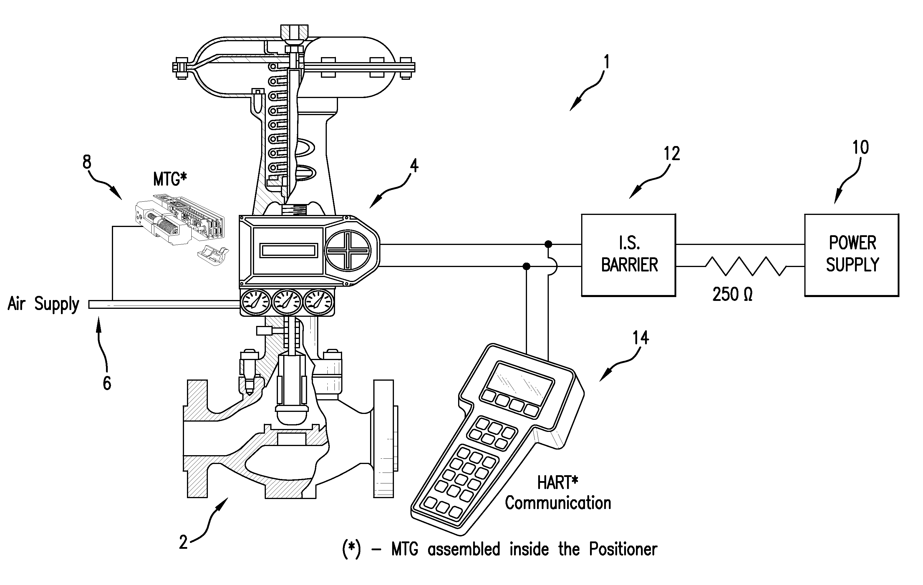
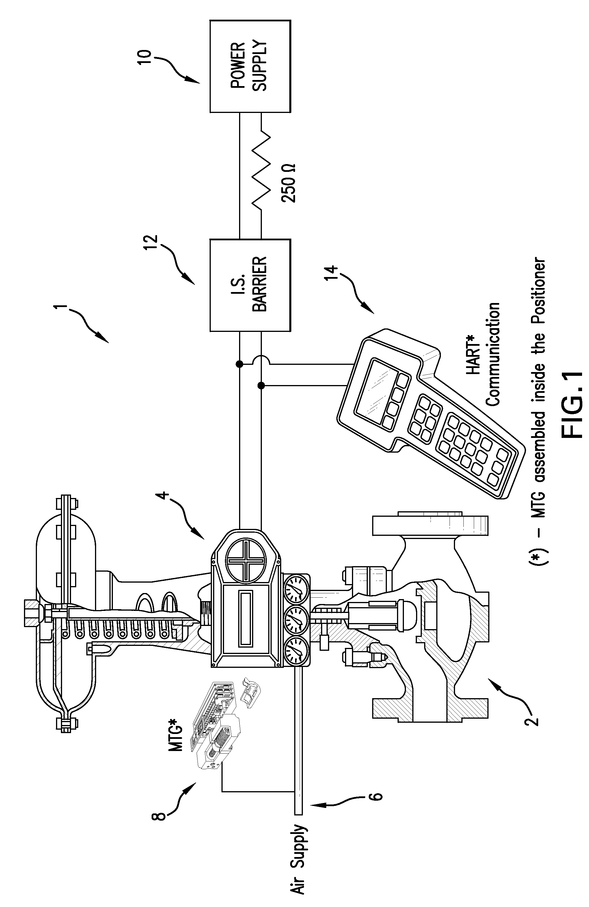
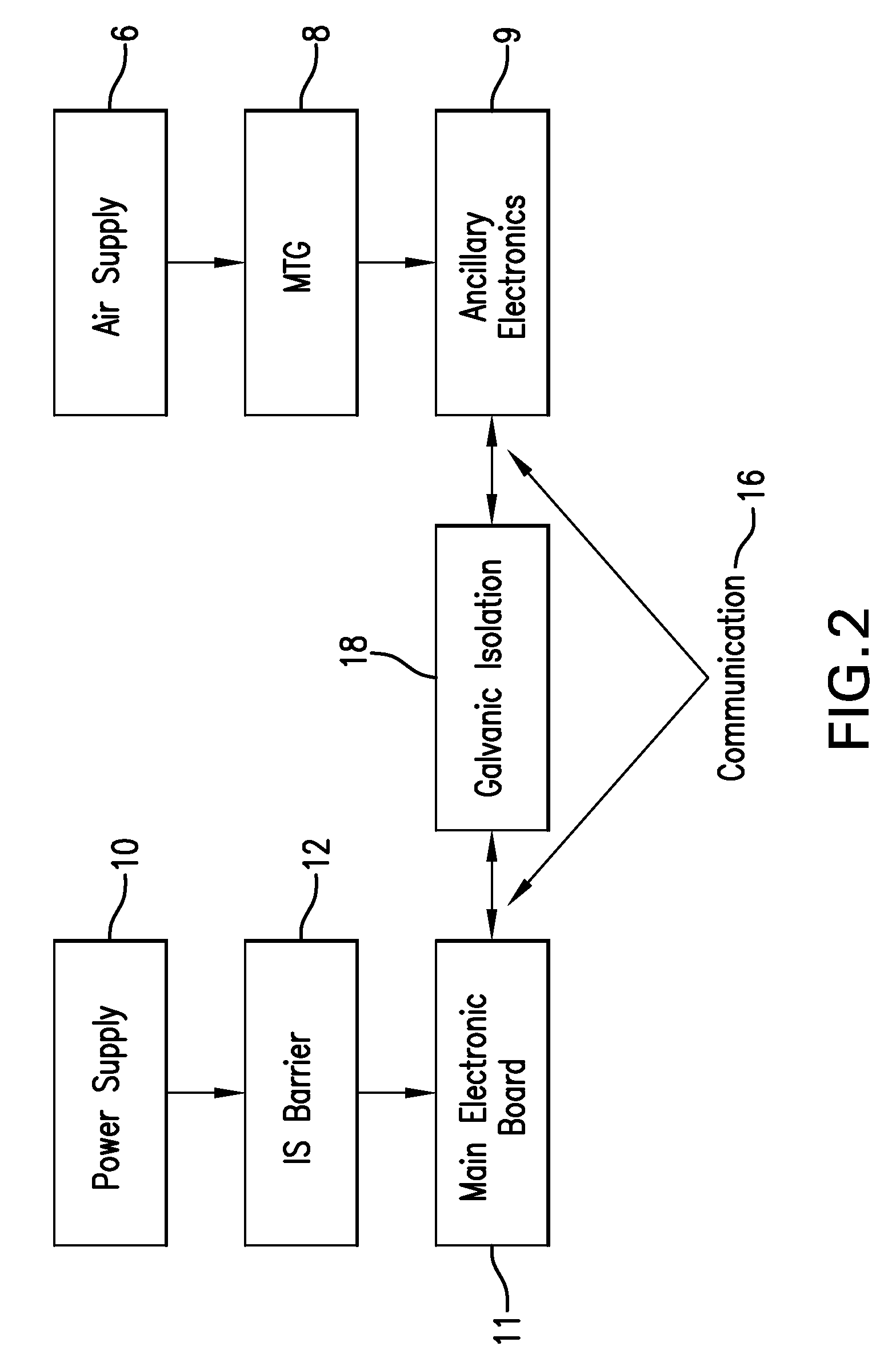
[0015]The disclosed system employs supplemental power generated by a micro-power generator (often called a micro-turbine generator (MTG)) that is powered by the same source of compressed air that is used to operate the pneumatic valve with which it is associated. The MTG provides additional power to any of a variety of field devices. This additional power is provided in parallel with a main power supply, and remains separate from the main power supply.

[0016]Referring to FIG. 1, a valve control system 1 is shown including a pneumatically operated globe valve 2, a pneumatic valve controller 4, a compressed air supply 6 for operating the pneumatic valve controller, an MTG 8 connected to the compressed air supply, a main power supply 10, an intrinsic safety (IS) barrier 12, and a field device 14. It will be appreciated that the IS barrier 12 may not be required in all applications, but is normally required for hazardous environment applications.

[0017]The main power supply 10 and MTG are...


PUM


Abstract

A micro-power generator is integrated in a pneumatic valve controller, such that the micro-power generator is powered by the same compressed air supply used to operate the valve. The micro-power generator includes a micro-turbine connected to a DC power generator, and a source of compressed air is used to drive the micro-turbine to generate power via the generator. The system may include a valve controller pneumatically connected to the compressed air supply. The valve controller may include electronics for displaying a condition of the controller. The system can include an electronic field device in communication with the valve controller for displaying a condition of the valve controller. The micro-turbine generator can be electrically connected to the field device to provide power to the electronic field device. Other embodiments are disclosed and claimed.

Description

CROSS-REFERENCE TO RELATED APPLICATIONS[0001]This is a non-provisional of pending U.S. provisional patent application Ser. No. 61 / 309,604, filed Mar. 2, 2010, the entirety of which application is incorporated herein by reference.FIELD OF THE INVENTION[0002]Embodiments of the invention generally relate to the field of valve controls, and more particularly to the field of micro-turbine power generation for enhancing functionality of valve control devices.DISCUSSION OF RELATED ART[0003]Many current valves are driven open and closed by pneumatic actuators. To be operable, such actuators require a continuous supply of compressed air. When such valves are addressed to be part of an automatic control loop (i.e., to support process automation), the valves are controlled (positioned) by means of valve positioners or solenoid valves called control devices.[0004]Control devices are used to open, close or modulate the position of the valve to which they are attached. In most cases these control...

Claims


Application Information

Patent Timeline
Patent Type & Authority Patents(United States)
IPC IPC(8): F16K31/02F01D15/00F01D15/10
CPCF01D15/00F01D15/10F05D2220/62F05D2220/20F05D2250/82
Inventor MINERVINI, LEOFERRAZ, WILLIAM D.
Owner WESTLOCK CONTROLS
Why Eureka
Try Eureka