Display apparatus light emission control method and display unit

a technology of light emission control and display apparatus, applied in the field of display apparatus, can solve the problems of inversely affecting display quality and the brightness of light emitting elements that are first driven in each cycle, and achieve the effect of reducing the amount of light intensity

Active Publication Date: 2015-03-03
NICHIA CORP
View PDF5 Cites 0 Cited by
  • Summary
  • Abstract
  • Description
  • Claims
  • Application Information

AI Technical Summary

Benefits of technology

[0017]To achieve the above object, a light emission control method according to a first aspect of the present invention controls a display apparatus that includes a display portion 10, a scanning portion 20, and a driving portion 30. The display portion 10 includes a plurality of light emitting elements 1 that are arranged in a matrix form. The scanning portion 20 is connected to a plurality of common lines C. Each of plurality of common lines C is connected to the anode terminals of corresponding elements of the plurality of light emitting elements 1 that are arranged in corresponding one of the rows of the display portion 10 so that the common lines C are scanned. The scanning portion 20 applies a voltage to selected one of the common lines C. The driving portion 30 is connected to a plurality of driving lines S. Each of the driving lines S is connected to the cathodes terminals of corresponding elements of the plurality of light emitting elements 1 that are arranged in corresponding one of the columns of the display portion 10. The driving portion 30 can drive selected elements of the plurality of light emitting elements 1 when one of the common lines corresponding to the selected elements is scanned by the scanning portion. The display apparatus displays an image in each cycle that includes a plurality of frames. All of the common lines C are scanned by the scanning portion 20 in each of the plurality of frames. One(s) of the rows in one frame in one cycle is / are driven. Other one(s) or the other rows are driven in a frame after the one frame in the one cycle. According to this construction, since different rows are driven in different frames in one cycle, it is possible to suppress the phenomenon where the parasitic capacitance of the driving line reduces the amount of light intensity of a particular row (dark line).
[0018]In a light emission control method according to a second aspect of the present invention, a non-light-emission period can be provided between a driving sub-frame in which a predetermined row(s) is / are driven and the next driving sub-frame in which other row(s) is / are driven. In the non-light-emission period, one or more common lines are scanned by the scanning portion and the driving portion prevents current flows in the light emitting elements. According to this construction, the periods for activation of the driving lines can be distributed. As a result, it is possible to reduce the duration of a non-light-emission period where the driving lines are deactivated so that the light emitting elements do not emit light. Therefore, it is possible to suppress the appearance of dark line.
[0019]In a light emission control method according to a third aspect of the present invention, the duration of a non-light-emission period can be constant. According to this construction, since the duration of a time period where electric charge is charged as the parasitic capacitances of the driving lines can be constant, the light emission amounts of the light emitting elements in the rows can be constant. Therefore, it is possible to prevent the phenomenon where light emitting elements in a particular row become darker.

Problems solved by technology

In this display unit control method, there is a problem that the brightness of light emitting elements that are first driven in each cycle may be smaller as compared with other light emitting elements.
For this reason, there is a problem that the darker light emitting elements may inversely affect the display quality.

Method used


Image

  • Display apparatus light emission control method and display unit
  • Display apparatus light emission control method and display unit
  • Display apparatus light emission control method and display unit

Examples


first embodiment

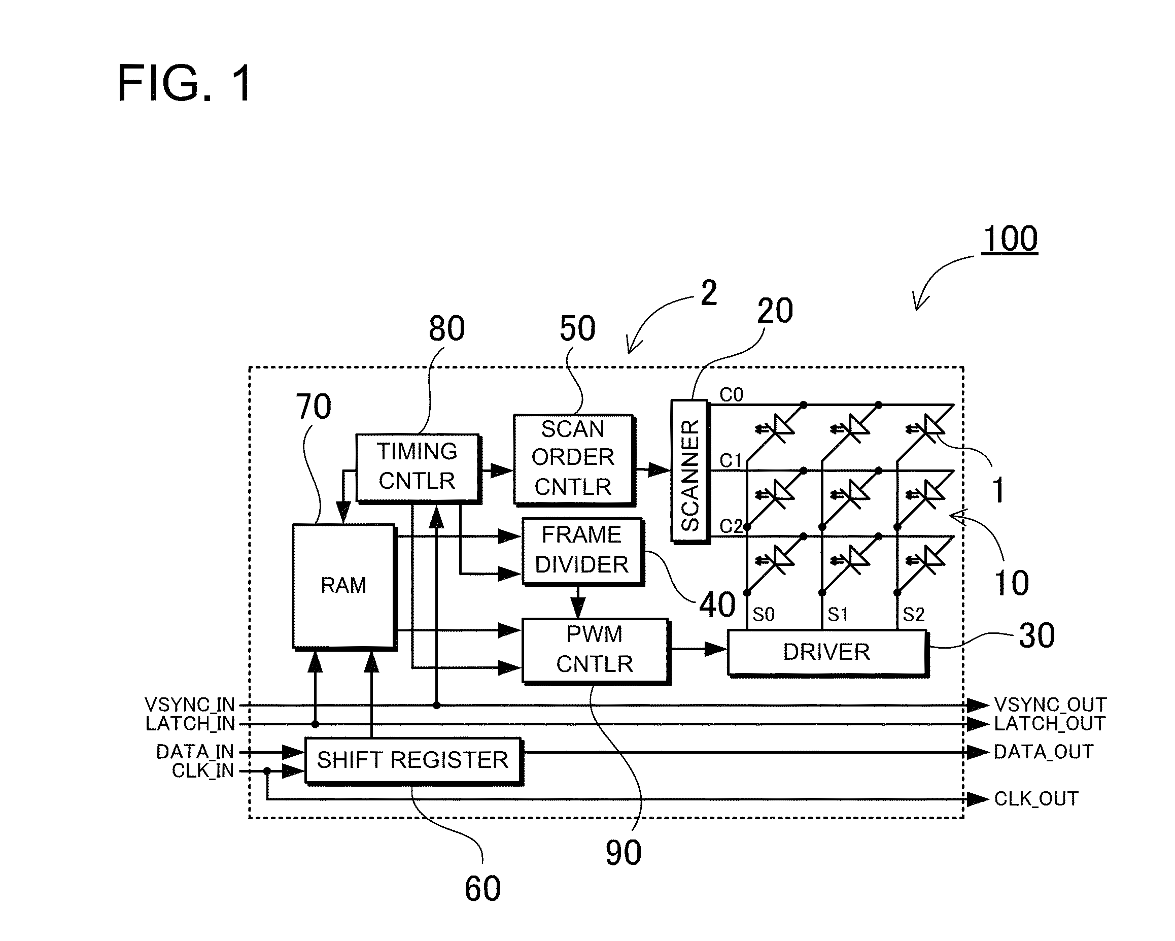
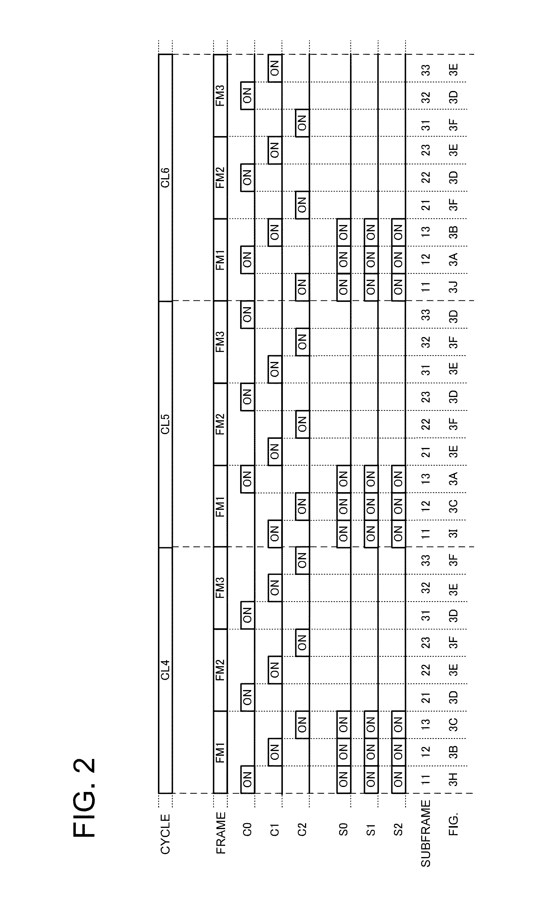
[0047]FIG. 1 is a block diagram showing a display unit 100 according to a first embodiment of the present invention. FIG. 2 is a timing chart showing a light emission control method for driving the display unit 100. FIGS. 3A to 3J are circuit diagrams showing current flows indicated by the arrows in the display unit in sub-frames shown in FIG. 2.

(Display Portion)

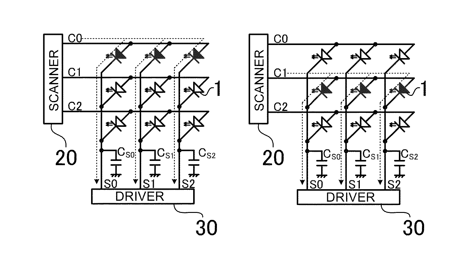
[0048]The display unit 100 includes a display portion 10 and a light emission control portion 2, as shown in FIG. 1. The display portion 10 includes a plurality of light emitting elements 1, a plurality of common lines C0 to C2, and a plurality of driving lines S0 to S2. The light emitting elements 1 are arranged in a matrix. Each of the common lines C0 to C2 is connected to the anode terminals of the light emitting elements 1 that are arranged in corresponding one of rows. Each of the common lines S0 to S2 are connected to the cathode terminals of the light emitting elements 1 that are arranged in corresponding one of colum...

second embodiment

[0059]The method according to the foregoing embodiment has been described to change the row that is first driven depending on cycles so that the dark line cyclically appears in different rows depending on cycles. In this method, the rows of the display portion 10 are driven in a first light emission order in a first cycle, while the rows of the display portion 10 are driven next to the first cycle in a second light emission order so that the row that is first driven in the second light emission order is different from the row that is first driven in the first light emission order. However, the present invention is not limited to this method. One(s) of the rows can be driven in one frame in one cycle, and other one(s) or the other rows can be driven in the one frame or a frame following the one frame in the one cycle. According to this method, the row that is first driven in each cycle can be also changed depending on cycles. As a result, it is also possible to suppress the dark line...

third embodiment

[0073]The foregoing second embodiment mentioned has been described to control the driving portion so that the activation timing period (a series of activation timing sub-frames) for activating the driving lines extends over frames, and the sub-frames for activating the driving lines continuously extend correspondingly to one frame. However, it is not necessary to control the driving line so that the sub-frames for activating the driving lines continuously extend correspondingly to one frame. The sub-frames for activating the driving lines can be distributed. FIG. 5 shows this type of control method according to a third embodiment. In this illustrated light emission control method, between the sub-frames where one row and the next rows are driven, the common lines are scanned, while the driving lines are deactivated (a non-light emission period are provided). That is, dissimilar to the foregoing first and second embodiments, a series of contiguous activation timing sub-frames for act...


PUM


Abstract

A light emission control method controls a display that includes a display portion, a scanning portion, and a driving portion. The display portion includes light emitting elements in a matrix form. The scanning portion is connected to common lines. Each common line is connected to the anode terminals of corresponding elements in corresponding row so that the common lines are scanned. The driving portion is connected to driving lines. Each driving line is connected to the cathodes terminals of corresponding elements in a corresponding column. The driving portion can drive selected elements when the common line corresponding to the selected elements is scanned. The method displays an image in each cycle including frames. All common lines are scanned in each frame. A part of the rows in one frame in one cycle is / are driven. Other part is driven in a frame after the one frame in the one cycle.

Description

BACKGROUND OF THE INVENTION[0001]1. Field of the Invention[0002]The present invention relates to a display unit that employs light emitting elements arranged in a matrix, and a light emission control method for a display apparatus that employs the display units.[0003]2. Description of the Related Art[0004]Display units that employ light emitting diodes (LEDs) as light emitting elements, and display apparatuses that employ the display units have been manufactured. For example, a large display apparatus can be constructed of a plurality of display units that cooperate with each other. In the case where a display unit is constructed in a matrix with m rows and n columns for example, the anode terminals of LEDs that are arranged in each row are connected to corresponding one common line, while the cathode terminals of LEDs that are arranged in each column are connected to corresponding one driving line. The common lines of m rows are cyclically turned ON one by one at a predetermined su...

Claims


Application Information

Patent Timeline
Patent Type & Authority Patents(United States)
IPC IPC(8): G09G3/32G09G3/20G09G5/10
CPCG09G3/32G09G5/10G09G3/2025G09G2300/06G09G2310/0202
Inventor MATSUMOTO, MAKOTO
Owner NICHIA CORP
Why Eureka
Try Eureka