Instrument and method for measuring the loss factor of an electrical apparatus

a technology of loss factor and instrument, which is applied in the direction of instruments, dielectric property measurements, electric devices, etc., can solve the problems of sensitivity of the sensors used to detect, the technique cannot be used on the apparatus which is in service, that is, liv

Inactive Publication Date: 2015-03-03
TECHIMP TECHNOLOGIES SA
View PDF18 Cites 0 Cited by
  • Summary
  • Abstract
  • Description
  • Claims
  • Application Information

AI Technical Summary

Benefits of technology

[0037]Thus, this invention makes it possible to calculate the loss factor with an excellent degree of precision and in a highly reliable manner, by measuring two magnetic field signals at two separate sections of the apparatus in order to then derive a signal given by the difference between the two signals, apply the Fourier transform to it and, as a function of the data obtained, directly calculate the value of the loss factor.
[0042]Moreover, the invention comprises suitable means for making the magnetic field sensors immune from noise outside the apparatus.
[0045]This makes it possible to obtain loss factor values which are comparable with the values obtained on any other apparatus, that is to say, having an absolute value.

Problems solved by technology

This technique has the disadvantage of being relatively unreliable and imprecise, since the leakage current normally has a very low intensity, thus posing a problem of sensitivity for the sensors used to detect it.
Another disadvantage is that this technique cannot be used on apparatus which is in service, that is, live, but only on apparatus which is out of service (offline measurements).
First of all, it is not very reliable since the field measurement is influenced by noise outside the cable. Further, this technique is not applicable online, that is to say, when the cable is live.
However, WO2007 / 068221 does not provide any teaching for measuring the loss factor.
However, the above described method is quite complicated because it needs to connect a plurality of devices / apparatus (e.g. the variable frequency generator) to the ends of the power cable.

Method used


Image

  • Instrument and method for measuring the loss factor of an electrical apparatus
  • Instrument and method for measuring the loss factor of an electrical apparatus
  • Instrument and method for measuring the loss factor of an electrical apparatus

Examples


Embodiment Construction

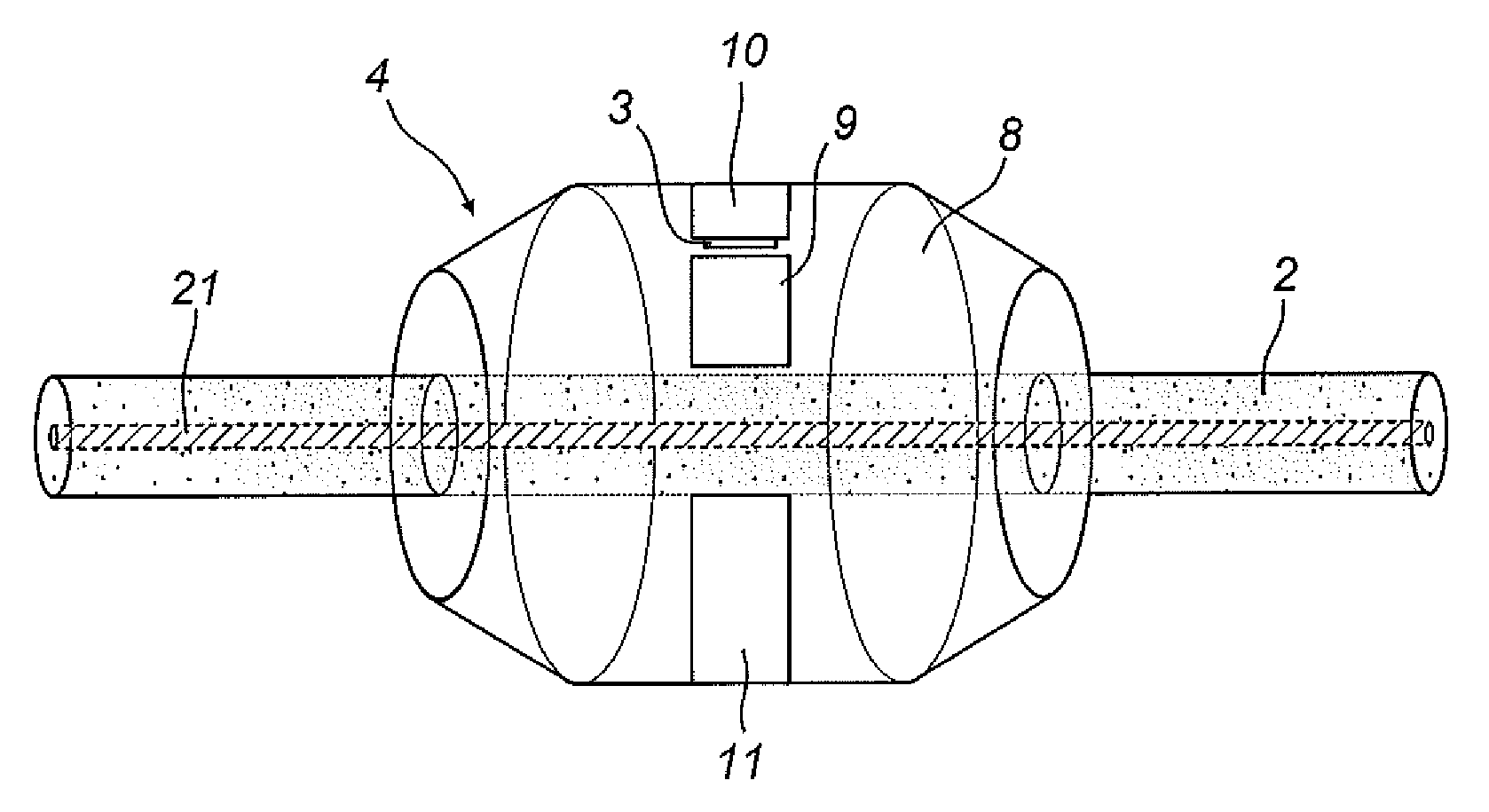
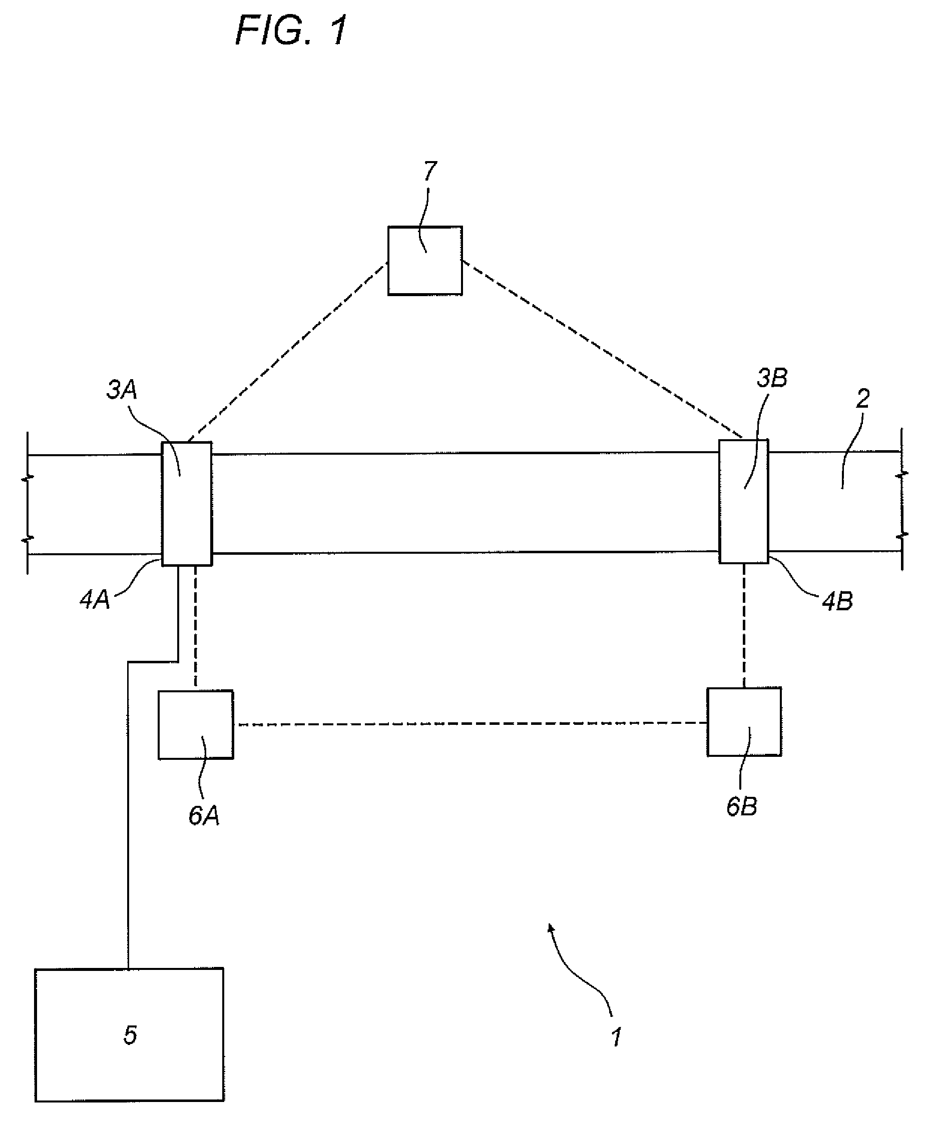
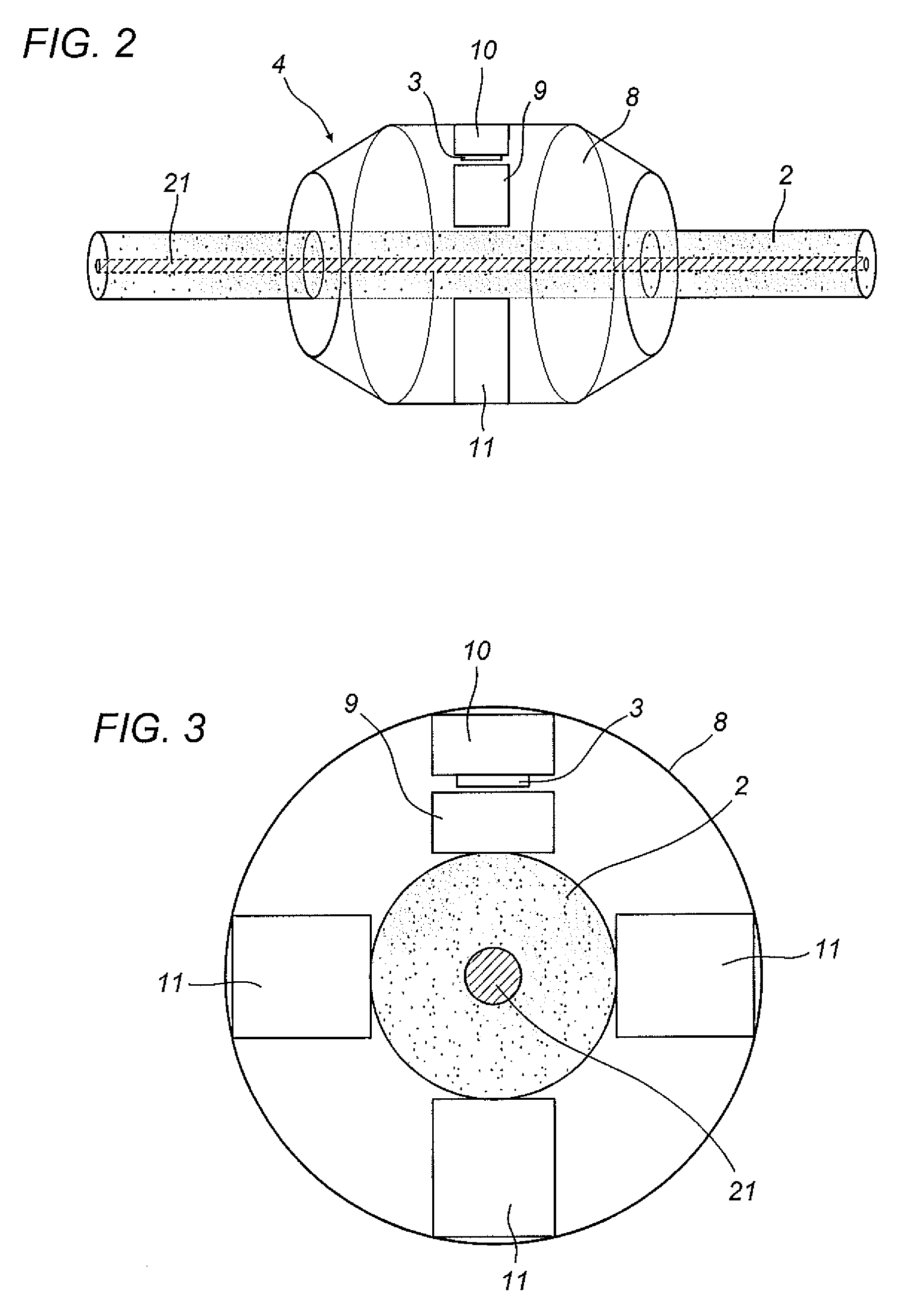
[0052]The numeral 1 in the drawings denotes an instrument for measuring the loss factor of an electrical apparatus 2 having an axially extending elongate geometry.

[0053]More specifically, the apparatus 2 is an electrical cable (for transmitting electrical power).

[0054]According to the invention, the instrument 1 comprises at least a first sensor 3A and a second sensor 3B connectable to the apparatus 2 in a first measuring section 4A and a second measuring section 4B, respectively.

[0055]The first and second measuring sections 4A and 4B are axially spaced along the apparatus 2 by a predetermined quantity (the quantity may be any quantity but it must be known; in other words, the sensors may be positioned at any distance from each other provided the distance is known).

[0056]The first and the second sensor 3A and 3B are configured to measure respective values of the magnetic field generated outside the apparatus 2 by a load current flowing axially through the apparatus 2.

[0057]It should...


PUM


Abstract

An instrument (1) for measuring the loss factor of an electrical apparatus (2) having an axially extending elongate geometry, in particular a medium voltage cable, comprises: at least a first and a second sensor (3A, 3B) connectable to the apparatus (2) in a first and a second measuring section (4A, 4B) axially spaced along the apparatus (2) by a predetermined quantity, respectively, and designed to measure respective values of the magnetic field generated outside the apparatus (2) by a load current flowing axially through the apparatus; a processing unit (5) designed to receive the magnetic field values measured by the sensors (3A, 3B) and programmed to derive from them a load loss value as a function of the difference between the measured magnetic field values.

Description

TECHNICAL FIELD[0001]This invention relates to an instrument and a method for measuring the loss factor of an electrical apparatus having an axially extending elongate geometry.[0002]More specifically, the invention relates to an instrument and a method for measuring the loss factor in an electric cable, especially in an electrical cable.BACKGROUND ART[0003]The loss factor—also known as loss angle or tan delta—is a measure of the deviation of the electric behaviour of a real capacitor with respect to that of a perfect system.[0004]In effect, the current flowing through a perfect capacitor with an alternating voltage applied to it (which can be represented in a plane by a vector) is in quadrature relative to the voltage, that is to say, it corresponds to a vector displaced at 90 degrees from the voltage vector.[0005]In a real capacitor, on the other hand, comprising a dielectric material which is not perfect (and whose conductance is therefore not zero), the voltage and current are d...

Claims


Application Information

Patent Timeline
Patent Type & Authority Patents(United States)
IPC IPC(8): G06F11/00G01R27/26G01R31/58
CPCG01R27/2694G01R31/021G01R31/025G01R31/58G01R31/52G01R27/26G01R31/08
Inventor SERRA, STEFANOMONTANARI, GIAN CARLO
Owner TECHIMP TECHNOLOGIES SA
Why Eureka
Try Eureka