Supercharge Your Innovation With Domain-Expert AI Agents!

Air conditioning apparatus with a controller that utilizes two set temperature ranges

a technology of air conditioner and controller, which is applied in the field of air conditioners, can solve the problems of increasing the cost of the air conditioner main unit, increasing the cost of the air conditioner, and making the occupants uncomfortable in the room

Inactive Publication Date: 2015-03-10
MITSUBISHI ELECTRIC CORP
View PDF12 Cites 14 Cited by
  • Summary
  • Abstract
  • Description
  • Claims
  • Application Information

AI Technical Summary

Benefits of technology

This solution provides energy-saving, comfortable heating by efficiently distributing warm air around the room without an expensive sensor, ensuring occupant comfort and reducing costs.

Problems solved by technology

For this reason, even if an occupant is actually present in the room, such an air-conditioning apparatus performs control so as to set the air blow vane to a downward direction or increase the air volume of the fan when a timer or home control is activated, which makes the occupant in the room uncomfortable.
However, such a system becomes costly due to the use of such an expensive infrared sensor.
In addition, in order to provide a highly precise detection, an optimum sensor mounting position must be selected with keeping structural and design restrictions in mind, resulting in increased cost of the air-conditioning apparatus main unit itself.

Method used


Image

  • Air conditioning apparatus with a controller that utilizes two set temperature ranges
  • Air conditioning apparatus with a controller that utilizes two set temperature ranges
  • Air conditioning apparatus with a controller that utilizes two set temperature ranges

Examples


embodiment 1

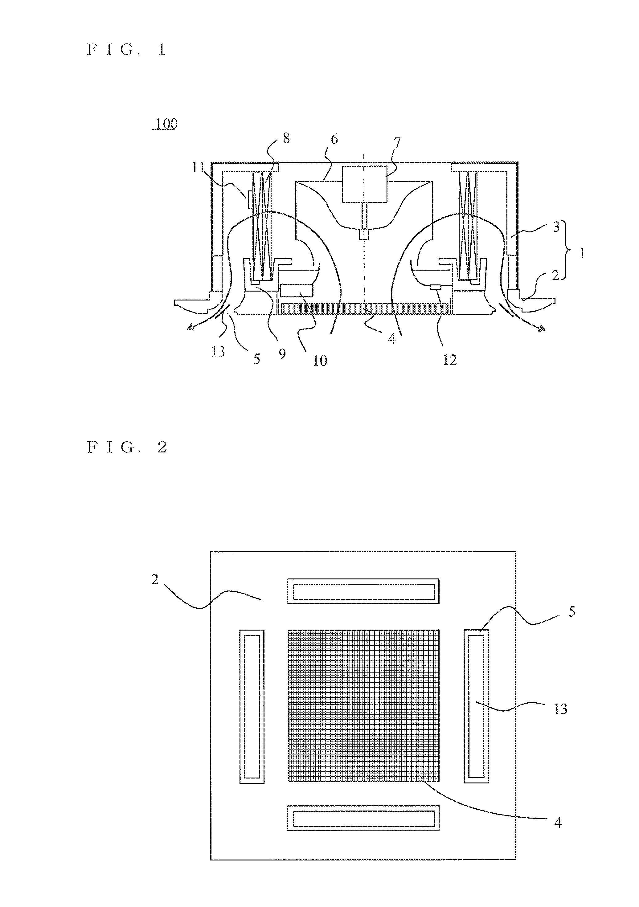
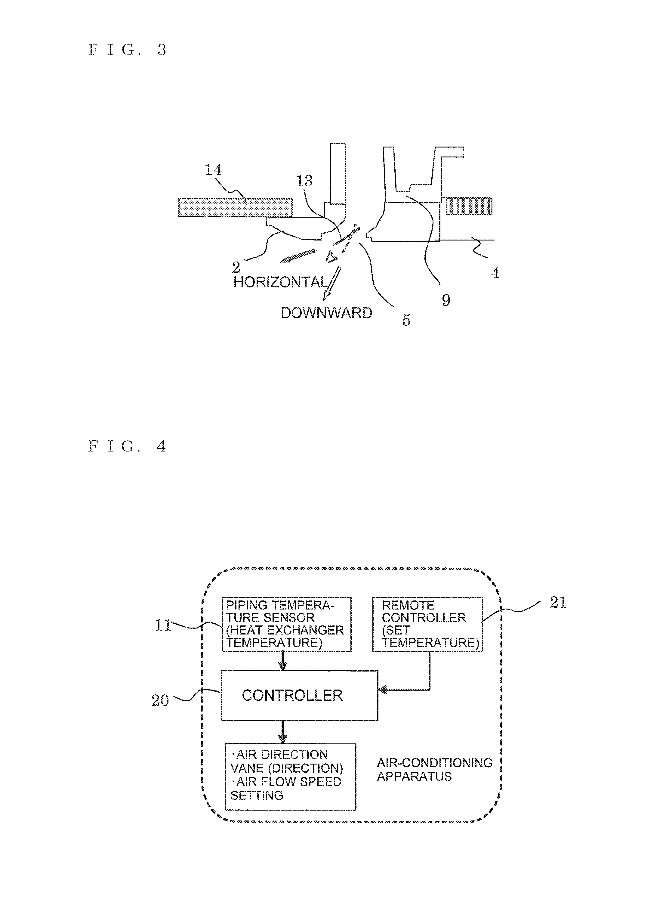
[0021]FIG. 1 a cross-sectional view of an air-conditioning apparatus according to Embodiment 1 of the present invention. FIG. 2 is a bottom view of a ceiling-mounted air-conditioning apparatus of FIG. 1. FIG. 3 is an expanded sectional view showing the cross section of an air outlet in the ceiling-recessed type air-conditioning apparatus of FIG. 1. The arrows in FIG. 1 indicate the directions in which air flows.

[0022]The air-conditioning apparatus (indoor unit) 100 according to Embodiment 1 is mounted in a ceiling of a room and takes in indoor air through an inlet 4 formed in the middle of a decorative panel 2 of a main unit 1 and blows out the air (air-conditioned air) subjected to heat exchange into the room through outlets 5 provided in four directions in the decorative panel 2, thereby air-conditioning (heating or cooling) the room.

[0023]The main unit 1 includes of the decorative panel 2 embedded in a ceiling material 14 with no clearance therebetween and a casing 3 in which maj...

embodiment 2

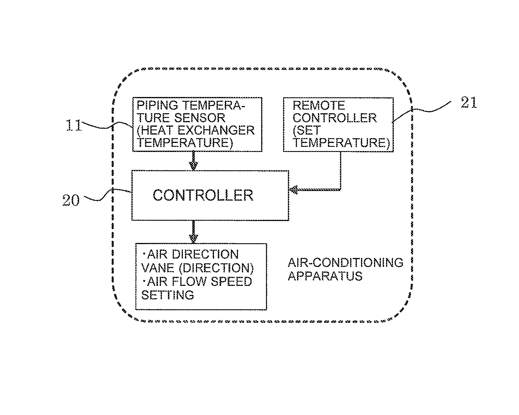
[0035]In Embodiment 2, the speed of the blower fan 6 is mainly controlled according to a temperature set via the remote controller 21 although the direction of the aft blow vane 13 is changed according to the temperature set via the remote controller 21 in Embodiment 1. Embodiment 2 is described below with reference to the flowchart of FIG. 7. FIG. 7 is a flowchart showing the control operation associated with heating operation of the air-conditioning apparatus according to Embodiment 1 of the present invention, which is basically the same as those of FIG. 5. The configuration of the controller 20 according to Embodiment 2 is the same as that of FIG. 4.

[0036]If a temperature set via the remote controller 21 falls within the higher range (between 17 and 28 degrees C.), it is determined that an occupant is present and thus normal heating operation is to be performed. If the temperature of the heat exchanger 8 detected by the piping temperature sensor 11 is found to be not more than 35...


PUM


Abstract

An air-conditioning apparatus includes a temperature sensor for detecting a heat exchanger temperature or an inlet air temperature, a controller that performs variable control of the direction of the indoor unit air blow vane or the air flow speed or rate of the blower fan, and a remote controller that remote-controls indoor unit operation, wherein temperatures set via the remote controller are divided into two set temperature ranges and during heating operation the controller sets at least the air blow vane to a horizontal or downward direction on the basis of the two set temperature ranges and the heat exchanger temperature or the inlet air temperature.

Description

BACKGROUND OF THE INVENTION[0001]1. Field of the Invention[0002]The present invention relates to air-conditioning apparatuses and, more particularly, it relates to an air-conditioning apparatus that, without a sensor provided to detect the presence of an occupant in a room, provides variable control of the direction of an air blow vane or the air flow speed or air volume of a fan associated with heating operation according to the circumstances.[0003]2. Description of the Related Art[0004]Some known air-conditioning apparatuses perform control so as to set the air blow vane on the indoor unit air outlet to a downward direction or increase the air volume of the indoor unit fan if there is a high likelihood that there is no occupant in the room when a timer or home control is activated (see, for example, Japanese Unexamined Patent Application Publication No. 61-223448). This is intended to speed up a rise in room temperature during heating operation if there is no occupant in the room....

Claims


Application Information

Patent Timeline
Patent Type & Authority Patents(United States)
IPC IPC(8): F01P7/02F25D17/04F24F11/04F28F27/00F24F7/00B60H1/03B60H1/00F25D17/00B60H1/22F24F1/00F24F11/00F24F11/76F24F13/06
CPCF24F1/0014F24F11/0012F24F11/0078F24F11/0079F24F2001/0037F24F2011/0045F24F2011/0068F24F2013/0616Y02B30/746F24F11/30F24F2110/10F24F2140/20F24F11/56F24F11/79F24F11/77F24F1/0047Y02B30/70F24F11/61F24F2120/00F24F11/46
Inventor KANAYA, OSAMUHATTORI, TARO
Owner MITSUBISHI ELECTRIC CORP
Features
  • R&D
  • Intellectual Property
  • Life Sciences
  • Materials
  • Tech Scout
  • Unparalleled Data Quality
  • Higher Quality Content
  • 60% Fewer Hallucinations
Learn More