Biomorphic wave energy collector

a technology of biomorphic wave and energy collector, which is applied in the direction of positive displacement liquid engine, electric generator control, piston pump, etc., can solve the problem of decrementing the physical space between the two parallel plates, and achieve the effect of increasing flexibility, increasing flexibility, and adding more stiffness and strength

Active Publication Date: 2015-03-10
ROSS GARY
View PDF6 Cites 2 Cited by
  • Summary
  • Abstract
  • Description
  • Claims
  • Application Information

AI Technical Summary

Benefits of technology

[0014]There are several materials that can be used for the present invention that meet the previously stated requirements. By way of example, the plates of the present invention may be constructed of aircraft aluminum or stainless steel. Also, there are many flexible materials from which the bladder may be made. The flotation means should be constructed of material that can bring the plates aggressively back to the start position, perpendicular to the plain of the pipes to which the present invention is attached. While the present invention may be of any size necessary to fulfill its function, the wave energy collectors of an embodiment for an active wave environment are preferably six to twelve feet wide and four to eight feet tall. The plumbing can be in several hoses. Multiple replaceable one-way flapper valves are located on one or both plates that will allow water to enter easily and quickly and stop flow when pressure on the inside of the bladder is higher than the outside pressure. The one way valves, as well as the bladder, should be durable, and also be easily replaceable.Low Surf Design
[0015]The embodiments of the present invention for a mild or low surf environment is preferably a more vertical design that is attached on one location to one conduit. While the embodiment may take on any form necessary to complete its function, the preferred embodiment is four to twelve feet tall and twenty-four to thirty-six inches wide. It may be made from a molded form and the preferred embodiment has the general appearance of a frond from a sea water plant. The top of the frond has a “bulb” and “petals” or “leaves” and the “stem” portion of the frond contains the bladder. The flotation means may be in the bulb, the petals or leaves, or both. The bulb also houses at least a one-way valve. Similar to the previously discussed embodiment, when there is little or no current, the flotation means will bring the wave energy collector upward. When there is wave movement, this embodiment is forced to bend to one side. As this embodiment is forced to one side, it will bend and this bending decreases the inner volume of the bladder. The water will be forced out the open hose that goes out the bottom of the wave energy collector and to the shore. The absence of force will create suction with even a slight difference of water pressure inside the collector compared to outside the collector, thus allowing the water to refill the bladder for the next cycle. Additionally, springs, stiffeners, or an outside post may be included to facilitate the compression of the bladder of this embodiment.

Problems solved by technology

This results in decreasing the physical space between the two parallel plates.

Method used


Image

  • Biomorphic wave energy collector
  • Biomorphic wave energy collector
  • Biomorphic wave energy collector

Examples


first embodiment

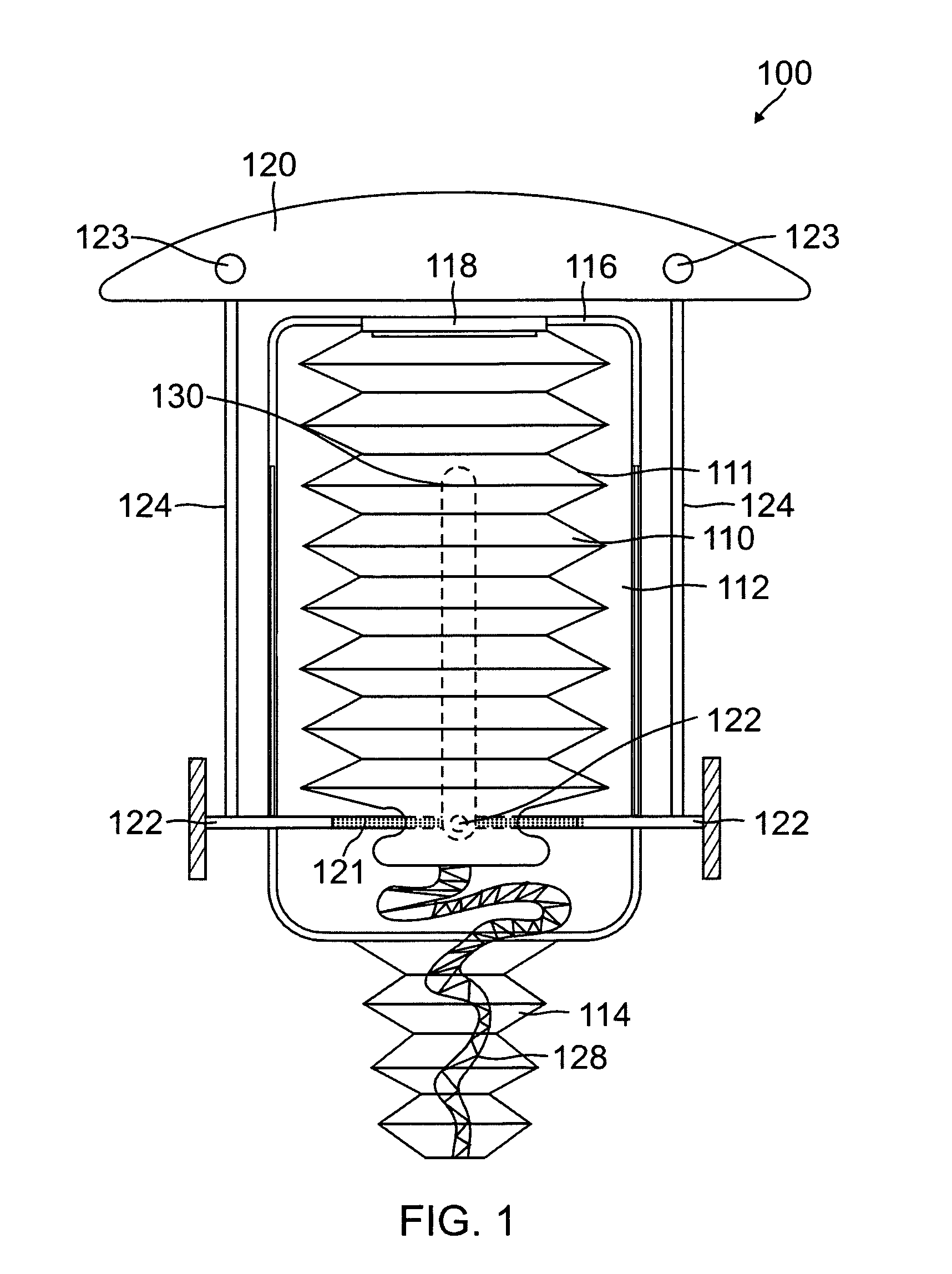
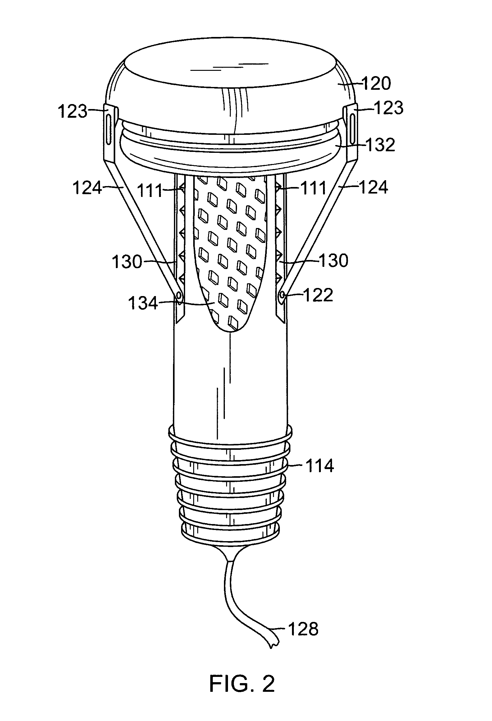
[0037]Referring now to FIGS. 1 and 2, there is shown the first embodiment, which is named the Hydroid design, of the present invention biomorphic wave energy collector. The Hydroid 100 has bladder 110, in a bellow-like shape, residing in a tubular housing 112. The bladder 110 of the Hydroid 100 has pleats 111 that allow the bladder to easily compress and expand. The bladder 110 shown in FIG. 1 illustrates the bladder 110 fully expanded. The top 116 contains a one-way valve 118. The bladder 110 is attached to the housing 112 at the top 116 of the housing 112 at the point where the one-way valve 118 resides, which allows sea water to enter the bladder 110. The bladder 110 also has an outlet 128, which leads toward shore and is preferably a hose-like device.

[0038]The housing 112 has a flexible bottom 114 which can attach to a conduit and which must be strong enough to withstand tidal and wave forces. Passing through the bottom 114 of the housing 112, is an outlet 128 that runs from the...

second embodiment

[0041]Referring now to FIGS. 3 through 10, there is shown the present invention, designated the Frond 200, illustrating one full cycle of the Frond 200 beginning with full expansion, as illustrated in FIGS. 3 and 4, and ending with full compression, as illustrated in FIGS. 7 and 8.

[0042]The Frond 200 has a bulbous top 245 with a neck 266. Inside the bulbous top 254 is at least one one-way intake valve 242 covered by a fish screen 244. The bulbous top may have petals 246, as shown in FIG. 3, or may not, as shown in FIGS. 5, 7 and 9. A flotation means may reside in the bulbous top 245, the petals 246, the neck 266, or any combination thereof. A deformable, oval-shaped bladder 250 extends the length from the neck 266 to an attachment means 251, where the Frond 200 is removeably attached, preferably to a conduit or pipe. Extending from the base of the deformable bladder 250, beyond the attachment means 251 is an outlet 256, which preferably runs the length of the above mentioned conduit...

third embodiment

[0047]Referring now to FIGS. 11, 12 and 13, there is shown the present invention, designated the Tivela 300. The Tivela 300 has two face plates 302, each of which have a base form 382 which is preferably of a rigid or stiff material and preferably has a curvilinear profile. The curvilinear profile is preferred because it is reminiscent of the shapes of sea life and sea creatures and will have less negative impact of the visual environment. Preferably on the exterior each face plate 302, on the base form 387, is a flotation means 384 and along the upper perimeter of each face plate 302 is an extra quantity of flotation means 304 such that it forms a rim 385 protruding on the exterior of each face plate 302. Along the bottom of each face plate 302 is at least one attachment means that allows swaying movement of the face plates 302, which is illustrated in FIGS. 11 through 13 as having a plurality of independent hinges 386 each attached to a corresponding base 387 for stability, and wh...


PUM


Abstract

An apparatus utilizing wave energy to capture ocean water and send it to shore for hydroelectricity, hydrodynamic energy conversion or desalination. The submerged device is located offshore and is preferably oriented orthogonal to the shoreline or the incoming water surges. Responding to underwater wave surges, a deformable bladder filled with sea water is compressed and the seawater contained therein is expelled and sent to shore. A one-way valve responds to the differential in water pressure inside the empty bladder as compared to outside the bladder and permits seawater to enter and refill the bladder. The bladder may have any of several forms including that of a bellows. The present invention discusses several ways by which the bladder may be compressed and several ways by which it can sense and respond to underwater wave surges.

Description

CROSS-REFERENCE TO RELATED APPLICATIONS[0001]This application claims priority from Provisional Patent Application Ser. No. 61 / 396,091 filed May 22, 2010.BACKGROUND OF THE INVENTION[0002]1. Field of the Invention[0003]Efforts for finding green energy have increased for many contemporary reasons. To this end, offshore energy has been explored and has become very developed, yet, inshore wave energy has not been a topic of much exploration. Inshore waves are energetic and offer more kinetic energy than offshore energy. The energetic inshore waves also offer more challenges and efforts on the part of inventors and developers, such as access to the shore and inshore environment, conservation concerns, pollution, fouling, and spoliation of the equipment, as well as the shore and inshore environment, and creating articles that can withstand a hostile and changing environment.[0004]2. Description of the Prior Art[0005]Historic attempts, as well as the best current attempts, have focused on v...

Claims


Application Information

Patent Timeline
Patent Type & Authority Patents(United States)
IPC IPC(8): F04B17/00F04B35/00F03B13/10F03B13/12H02P9/04F03B13/18
CPCF03B13/188Y02E10/38Y02E10/30Y02A20/144
Inventor ROSS, GARY
Owner ROSS GARY
Why Eureka
Try Eureka