Male member

a male member and a technology for preventing which is applied in the field of male members, can solve the problems of liquid substance leakage from male members, and achieve the effects of reducing the amount of liquid substance, preventing the liquid substance leakage from male members, and increasing the space capacity

Active Publication Date: 2015-03-10
JMS CO LTD
View PDF29 Cites 40 Cited by
  • Summary
  • Abstract
  • Description
  • Claims
  • Application Information

AI Technical Summary

Benefits of technology

[0016]According to the present invention, in the state where the outer peripheral wall of the cover is not deformed by compression, since the inner peripheral surface of the interior cavity of the head part blocks the lateral hole of the tubular member, it is possible to prevent the liquid substance leakage from the male member when the male member is not connected to the female member.
[0017]Further, in the state where the outer peripheral wall of the cover is not deformed by compression, the tip of the tubular member and the innermost part of the interior cavity with the slit are spaced apart from each other. Therefore, in a space formed between the tip of the tubular member and the innermost part of the interior cavity in the process of separating the male member from the female member, it is possible to generate negative pressure in accordance with the increase in the capacity of the space. The negative pressure draws into the space the liquid substance remaining between the cover and the female member. Consequently, it is possible to reduce the amount of the liquid substance adhering to the outer surface of the cover and the outer surface of the female member after separation of the male member and the female member.

Problems solved by technology

However, since the male luer is exposed to the outside before insertion into and after removal from the needle-less port, there is a possibility that the liquid substance leaks from the male luer.

Method used


Image

  • Male member
  • Male member
  • Male member

Examples


Embodiment Construction

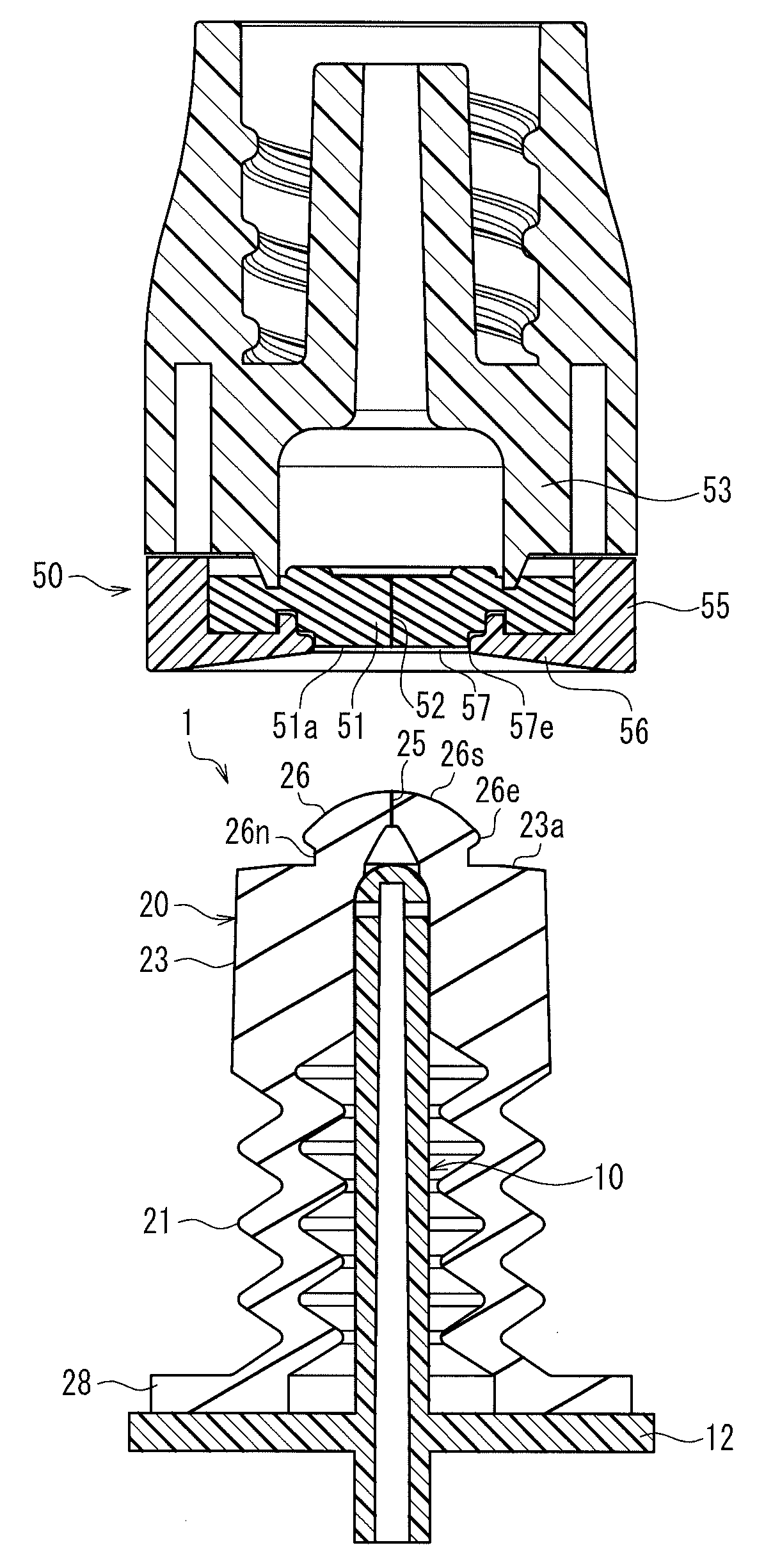
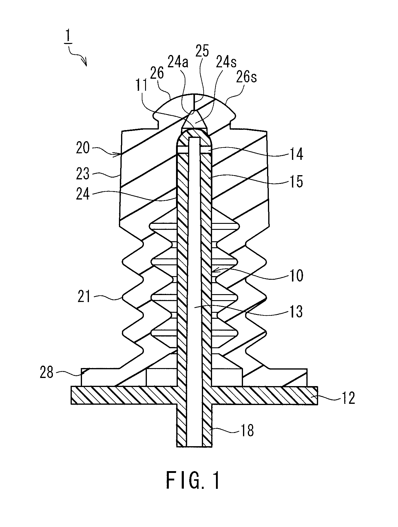
[0029]In order to investigate the cause of the liquid substance remaining on the outer surface 123a of the top plate 123 of the cover 120 and the outer surface 151a of the septum 151 after removal of the male luer 110 from the needle-less port 150 in the case of using the conventional male luer 110 equipped with the cover 120 shown in FIG. 7, the inventors of the present invention observed using an X-ray CT how the septum 151 and the cover 120 were deformed from the connection to the separation of the male luer 110 with respect to the needle-less port 150. The following describes the detail.

[0030]FIGS. 8A to 8D are cross-sectional views sequentially showing states where the conventional male luer 110 equipped with the cover 120 is inserted into the needle-less port 150. The slit 152 in the septum 151 and the slit 125 in the top plate 123 of the cover 120 are formed along a direction perpendicular to the cross section of the drawings.

[0031]FIG. 8A shows a state immediately before the...


PUM


Abstract

A male member (1) includes a tubular member (10) and a cover (20) covering at least a tip (11) of the tubular member. A lateral hole (14) that communicates with a flow path (13) is formed in an outer peripheral surface of the tubular member. The cover includes an outer peripheral wall (21) that can be deformed elastically by compression and a head part (23) that is provided at one end of the outer peripheral wall. The head part includes an interior cavity (24) into which the tubular member is inserted, and a slit (25) is formed in an innermost part (24a) of the interior cavity. In a state where the outer peripheral wall is not deformed by compression, an inner peripheral surface of the interior cavity contacts closely with the outer peripheral surface of the tubular member so as to block the lateral hole, and the tip of the tubular member and the innermost part of the interior cavity are spaced apart from each other. Thereby, it is possible to reduce an amount of a liquid substance adhering to outer surfaces of the cover and a female member after separation from the female member.

Description

TECHNICAL FIELD[0001]The present invention relates to a male member that includes a tubular member in which a flow path for carrying a liquid substance is formed and a cover that covers at least a tip of the tubular member.BACKGROUND ART[0002]In the case of a liquid transfusion and a blood transfusion to a patient and extracorporeal circulation in surgery, a path (transport line) must be formed for transporting a liquid substance, such as a drug solution and blood. The transport line generally is formed by connecting vessels, various instruments, tubes, etc. As a method for connecting different members, there has been known a slip connection between a male luer as a male member and a needle-less port as a female member (for example, see Patent Documents 1, 2). The needle-less port includes a partition member (hereinafter, referred to as “septum”) made of an elastic material such as rubber, with the middle formed with a linear slit (cut). By inserting a male luer (tubular body) to wh...

Claims


Application Information

Patent Timeline
Patent Type & Authority Patents(United States)
IPC IPC(8): A61M5/14A61M39/10A61M39/24F16L37/30
CPCA61M39/10F16L37/30A61M2039/1027A61M2039/1066A61M2039/2433A61M2039/2473Y10S604/905A61J1/14A61M39/02
Inventor TACHIZAKI, HITOSHIOKIYAMA, TADASHI
Owner JMS CO LTD
Why Eureka
Try Eureka