Connection structure of electronic component

a technology of electronic components and connecting structures, applied in the direction of connecting devices, contact members penetrating/cutting insulation/cable strands, lighting support devices, etc., can solve the problems of increasing the thickness of the connection structure in the vertical direction, and it is difficult to make the connection structure thinner, so as to reduce the thickness, reduce the thickness, and the effect of effective use of dead spa

Inactive Publication Date: 2015-03-17
YAZAKI CORP
View PDF13 Cites 9 Cited by
  • Summary
  • Abstract
  • Description
  • Claims
  • Application Information

AI Technical Summary

Benefits of technology

[0008]The present invention has been made considering the problem, and an object of the present invention is to provide an electronic-component connection structure capable of enabling a reduction in thickness.
[0014]According to the electronic-component connection structure in the first aspect of the present invention, each terminal of the pair of terminals is not required to protrude a fixing means in a vertical direction, and it is possible to fix the terminals in the housing by effectively using the dead space between the protrusion pieces and the contact pieces. Therefore, it is possible to fix the terminals in the housing without increasing a dimension in the vertical direction, and thus reduce the thickness.
[0015]Further, according to the electronic-component connection structure in the second aspect of the present invention, since the terminal-fixing part is formed at the side surface of the housing, it is possible to fix the terminals in the housing without increasing the dimension in the vertical direction.
[0016]Further, according to the electronic-component connection structure in the third aspect of the present invention, since the terminal-fixing part is formed at the surface of separation wall which divides the housing into two accommodation spaces, it is possible to fix the terminals in the housing without increasing the dimension in the vertical direction.
[0017]Furthermore, according to the electronic-component connection structure in the fourth aspect of the present invention, since the housing has an opened upper face, and the terminal-fixing parts clamp the protrusion pieces in cooperation with the bottom wall of the housing, it is not necessary to provide a wall at the upper face of the housing for fixing the terminals. Therefore, it is possible to fix the terminals in the housing without increasing a dimension in the vertical direction, and thus reduce the thickness.
[0018]Moreover, according to the electronic-component connection structure in the fifth aspect of the present invention, since each terminal-fixing part has the inclined surface having an upper end and a lower end which is closer to the bottom wall than the upper end, the lower end of the inclined surface being more separate away from the wall surface than the upper end, when each terminal of the pair of terminals is accommodated from over the housing into the housing, it is possible to easily dispose the protrusion pieces between the terminal-fixing part and the wall forming the bottom wall of the housing.

Problems solved by technology

However, in the electronic-component connection structure disclosed in JP-2007-149762A, since locking portions are formed at the terminals to protrude in a vertical direction of the device, and the terminals are fixed at predetermined positions on the bottom surface of the housing by the locking portions, a thickness of the connection structure in its vertical direction increases, and thus it is difficult to make the connection structure thinner.

Method used


Image

  • Connection structure of electronic component
  • Connection structure of electronic component
  • Connection structure of electronic component

Examples


embodiment

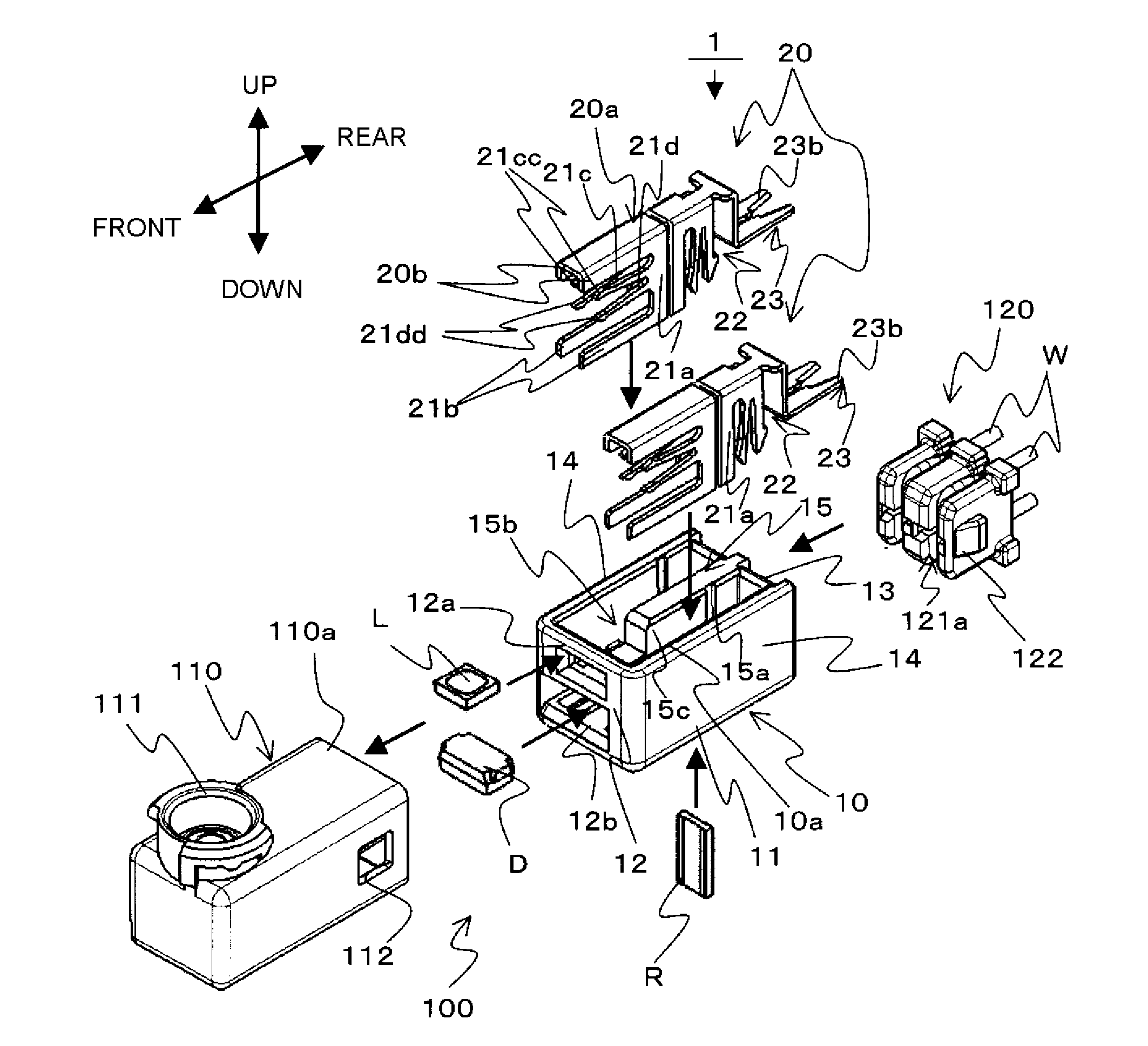
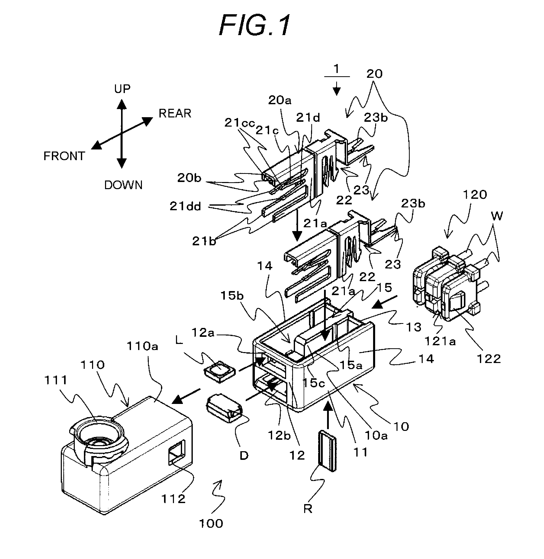
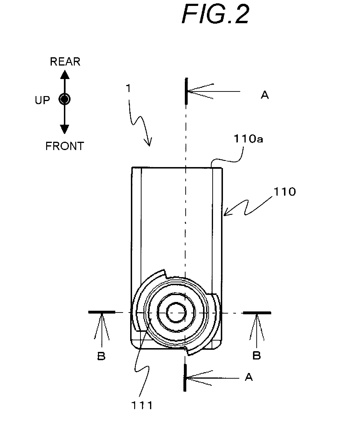
[0036]FIG. 1 is an exploded perspective view illustrating a structure of an LED lighting unit 100 having an electronic-component connection structure 1 according to an embodiment of the present invention. FIG. 2 is a top view of the LED lighting unit 100 with an electric-wire holding part 120 in FIG. 1 removed. FIG. 3 is a cross-sectional view of the LED lighting unit 100 shown in FIG. 2 as taken along line A-A. FIG. 4 is a cross-sectional view of the LED lighting unit 100 shown in FIG. 2 as taken along line B-B. FIG. 5 is a bottom view of the electronic-component connection structure 1 shown in FIG. 1. FIG. 6 is an enlarged perspective view of a housing 10 shown in FIG. 1. FIG. 7 is a cross-sectional view illustrating a portion of the housing 10 shown in FIG. 6. FIG. 8 is an enlarged perspective view of a terminal 20 shown in FIG. 1. FIG. 9 is a diagram for explaining details of the electric-wire holding part 120 shown in FIG. 1. FIG. 10 is a circuit diagram illustrating a circuit ...


PUM


Abstract

A connection structure includes a housing; terminals fixed in the housing; and an electronic component accommodated inside the housing and connected to the terminals. Each terminal includes: a base portion; a protrusion piece extending from the base portion in a lateral direction; and an elastic contact piece extending from the base portion in the lateral direction so that a distance between the protrusion piece and the elastic contact piece becomes shorter towards an end of the elastic contact piece separate away from the base portion. The housing includes a terminal-fixing part protruded from a wall surface of the housing at a position between the protrusion piece and the elastic contact piece near the base portion of the terminal to clamp and fix the protrusion piece between the terminal-fixing part and a wall of the housing.

Description

CROSS REFERENCE TO RELATED APPLICATIONS[0001]This application is a continuation of PCT application No. PCT / JP2011 / 079126, which was filed on Dec. 9, 2011 based on Japanese Patent Application (No. 2010-286238) filed on Dec. 22, 2010, the contents of which are incorporated herein by reference.BACKGROUND OF THE INVENTION[0002]1. Field of the Invention[0003]The present invention relates to a connection structure which electrically connects an electronic component by a terminal.[0004]2. Description of the Related Art[0005]In a connection structure of an electronic component (or an electronic-component connection structure) according to a related art which electrically connects electronic components by a pair of terminals, the pair of terminals are accommodated and fixed in a housing, and the electronic components are electrically connected by the pair of terminals. This electronic-component connection structure requires the reliability of the connection of the electronic components and t...

Claims


Application Information

Patent Timeline
Patent Type & Authority Patents(United States)
IPC IPC(8): H01R4/26H01R13/11H01R13/17H01R13/422H01R13/66H01R13/717H01R33/09
CPCH01R13/17H01R13/4223H01R13/66H01R13/6641H01R13/7175H01R33/09H01R13/6616H01R13/112F21V19/0015F21V21/002F21Y2115/10H01R13/422H01R13/717
Inventor MOCHIZUKI, SHINJI
Owner YAZAKI CORP
Why Eureka
Try Eureka