System for determining the orientation of a catheter

a catheter orientation and catheter technology, applied in the direction of catheters, prostheses, instruments, etc., can solve the problems of difficult time-consuming and complex and the detection of a single marker on the projection image does not allow the determination of the catheter orientation

Inactive Publication Date: 2015-03-17
KONINKLJIJKE PHILIPS NV
View PDF9 Cites 8 Cited by
  • Summary
  • Abstract
  • Description
  • Claims
  • Application Information

AI Technical Summary

Benefits of technology

[0004]It is an object of the present invention to provide a system for determining the orientation of a catheter, an asymmetric marker for attaching to a catheter for determining the orientation of the catheter, a catheter comprising the asymmetric marker, an orientation determination unit and methods and computer programs for determining the orientation of the catheter comprising the asymmetric marker, which allow a less complex and less time consuming determination of the orientation of the catheter.
[0011]Since the asymmetric marker is adapted such that the orientation of the asymmetric marker is determinable from the projection image of the asymmetric marker alone, it is not required to recognize different elements in the projection image, in particular, it is not necessary to recognize radial marker bands, a wedge-shaped asymmetric marker and the distal end of the catheter itself. One or several asymmetric markers can be attached to the catheter, wherein only this or these asymmetric markers have to be recognized in the projection image, i.e. it is not necessary to provide different recognition algorithms for different kinds of elements. This reduces the complexity and the time needed for determining the orientation of the catheter.
[0032]It is further preferred that the multitude of asymmetric markers is attached to segments of the catheter, wherein the orientation determination unit is adapted to determine the orientation of the multitude of asymmetric markers from the projection image and to determine the orientations of the segments of the catheter from the determined orientation of the multitude of asymmetric markers, wherein the orientation determination unit further comprises a catheter model providing unit for providing a model of the catheter and a catheter path determination unit for determining a path of the catheter by arranging the provided model of the catheter such that it corresponds to the determined orientations of the segments of the catheter. The catheter model is, for example, an elasto-mechanical model of the catheter, wherein it is assumed that the catheter can only be bent smoothly, i.e. without kinking.
[0039]It is further preferred that at least two of the asymmetric markers are rotated with respect to each other and with respect to a rotation axis located along the length and along the center of the catheter. This ensures that some asymmetric elements are always visible with little foreshortening regardless of the rotation of the catheter around its axis.

Problems solved by technology

This means the detection of a single marker on the projection image does not allow determining the orientation of the catheter, i.e. at least the radial marker bands, the distal end of the catheter and the asymmetrical marker have to be imaged.
This determination of the orientation of the catheter is very complex and time consuming.

Method used


Image

  • System for determining the orientation of a catheter
  • System for determining the orientation of a catheter
  • System for determining the orientation of a catheter

Examples


Embodiment Construction

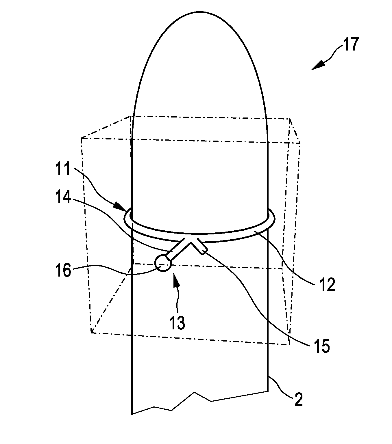
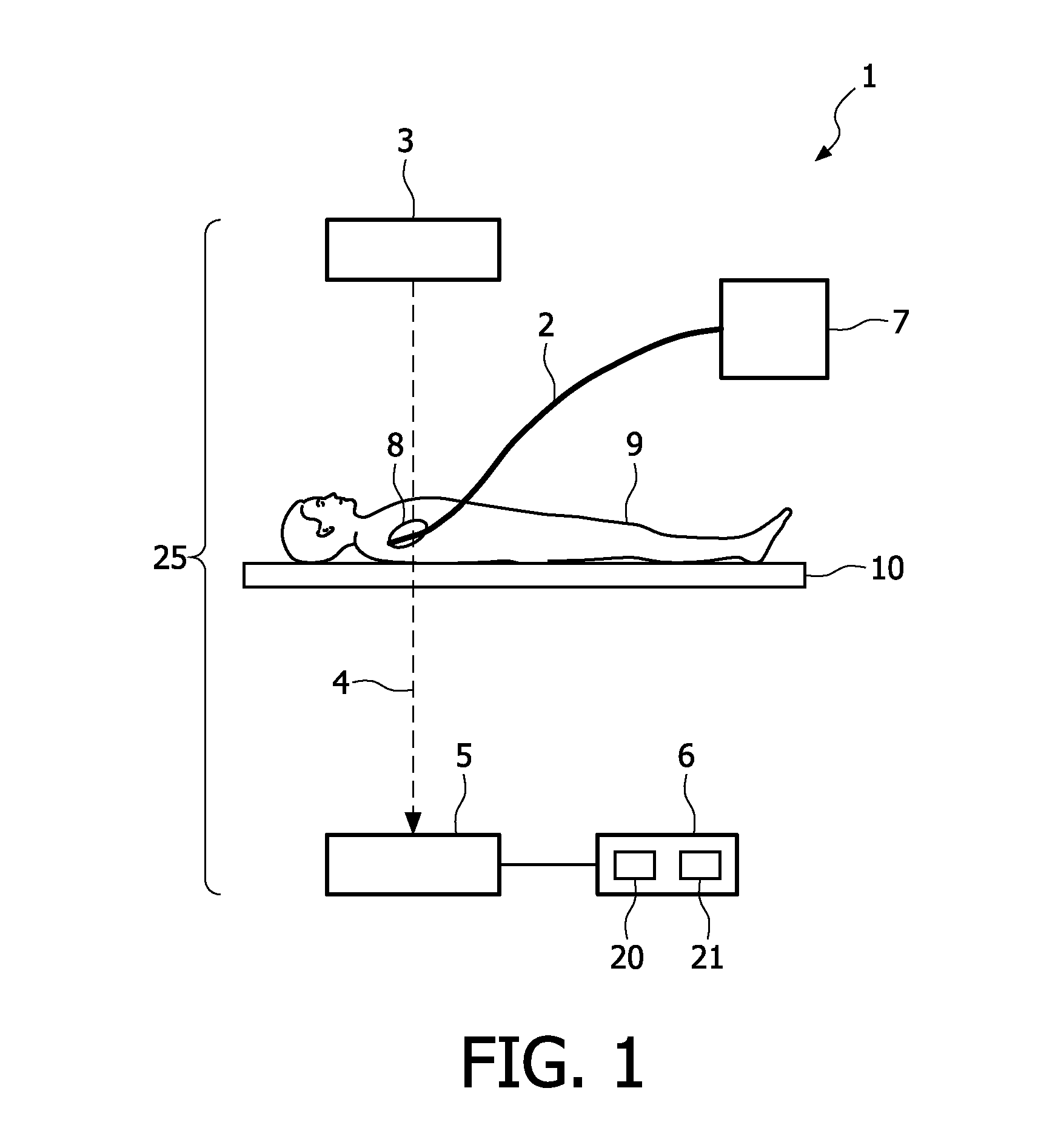
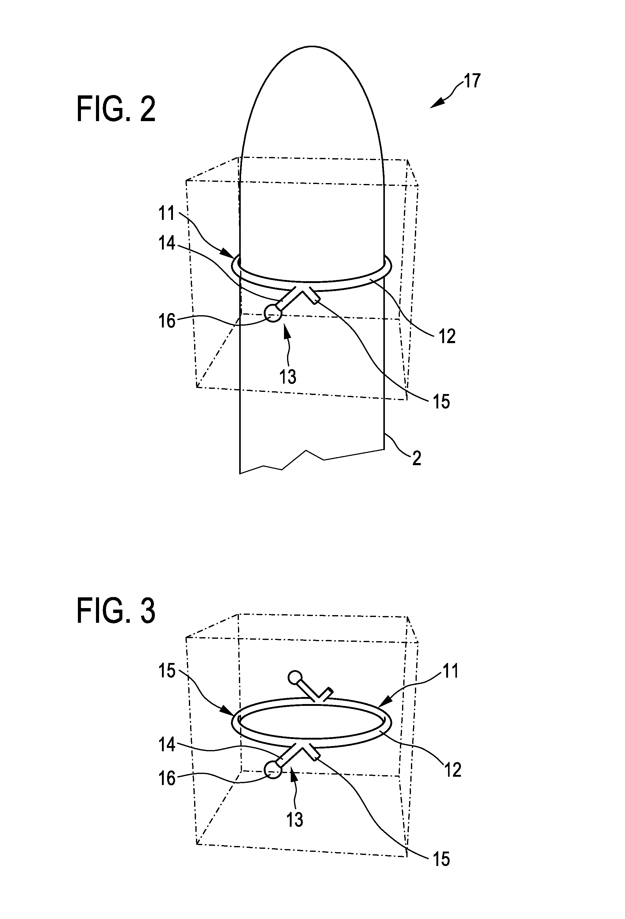
[0063]FIG. 1 shows schematically and exemplarily a system 1 for determining the orientation of a catheter 2. This system 1 comprises a catheter 2 and an asymmetric marker attached to the catheter. The asymmetric marker will be explained further below with reference to, for example, FIGS. 2 and 3. The system 1 for determining the orientation of the catheter 2 further comprises an imaging unit 25 for generating a projection image of the asymmetric marker, wherein the imaging unit 25 comprises a radiation source 3 for generating radiation 4 for projecting the asymmetric marker in a projection plane and a detection unit 5 for generating the projection image of the asymmetric marker projected in the projection plane.

[0064]The detection unit 5 comprises preferentially a two-dimensional detection surface, wherein the projection plane is located on the two-dimensional detection surface.

[0065]The imaging unit 25 comprising the radiation source 3 and the detection unit 5 is, in this embodimen...


PUM


Abstract

The present invention relates to a system for determining the orientation of a catheter (2). The system comprises a catheter (2), an asymmetric marker (11) attached to the catheter (2), and an imaging unit (25) for generating a projection image of the asymmetric marker (11), wherein the imaging unit (25) comprises a radiation source for generating radiation for projecting the asymmetric marker (11) in a projection plane and a detection unit for generating the projection image of the asymmetric marker (11) projected in the projection plane. The system comprises further an orientation determination unit for determining the orientation of the asymmetric marker (11) from the projection image of the asymmetric marker (11) and for determining the orientation of the catheter (2) from the determined orientation of the asymmetric marker (11). The asymmetric marker (11) is adapted such that the orientation of the asymmetric marker (11) is determinable from the projection image of the asymmetric marker (11) alone.

Description

FIELD OF THE INVENTION[0001]The present invention relates to a system for determining the orientation of the catheter, an asymmetrical marker for attaching to a catheter for determining the orientation of the catheter, a catheter comprising the asymmetric marker, an orientation determination unit and methods and computer programs for determining the orientation of the catheter comprising the asymmetric marker.BACKGROUND OF THE INVENTION[0002]U.S. Pat. No. 6,493,575 B1 discloses a system for determining the orientation of a catheter. Radial marker bands surround the distal end of the catheter at predefined intervals. Furthermore, an asymmetric marker being wedge-shaped is attached proximal to the distal end of the catheter. For determining the orientation of the catheter a projection image of the radial marker bands, the asymmetric marker and the distal end of the catheter itself is needed.SUMMARY OF THE INVENTION[0003]This means the detection of a single marker on the projection ima...

Claims


Application Information

Patent Timeline
Patent Type & Authority Patents(United States)
IPC IPC(8): A61B5/00G03B42/02A61B19/00A61F2/30A61M25/01
CPCA61B19/54A61F2002/30619A61M25/0108A61B2019/5238A61F2250/0098A61B2019/502A61F2250/0097A61B2034/102A61B2090/376A61B90/39A61F2002/30617
Inventor HANSIS, EBERHARD SEBASTIANGRASS, MICHAEL
Owner KONINKLJIJKE PHILIPS NV
Why Eureka
Try Eureka