Masonry wall wire reinforcement apparatus and methods thereof

a technology of wire reinforcement and masonry wall, which is applied in the direction of walls, building components, pillars, etc., can solve the problems of eye damage during shipping, difficulty in budgeting inventory purposes, and unnecessarily high cost, so as to reduce packaging costs and product damage when shipped, and minimize thermal energy transfer.

Inactive Publication Date: 2015-03-24
MECHANICAL PLASTICS CORP
View PDF9 Cites 15 Cited by
  • Summary
  • Abstract
  • Description
  • Claims
  • Application Information

AI Technical Summary

Benefits of technology

[0012]The present invention discloses a clip configured to be attached to the masonry wall wire reinforcement product for allowing the insertion of the pintle tie that will be attached to the veneer wall. The present invention may also utilize a separate thermal attachment to be attached or placed on the clip to act as a thermal break and reduce the transfer of energy, in the form of hot or cold temperatures, from travelling from the outside of the veneer wall to the inside of the masonry wall.
[0013]The present invention allows for a reduction in parts in inventory, while still allowing the ability to generate the same number of different types and size masonry wall wire reinforcement products for different job requirements. By attaching the correct sized clip (and / or thermal attachment) to the wire reinforcement product, usually at the job site, many different sized masonry wall wire reinforcement products can be produced from fewer components.
[0015]Accordingly, and in accordance with the present invention, a masonry wall wire reinforcement apparatus and system is provided that includes a clip containing grooves at one end that receive and support the wires of a ladder type or truss type masonry wall wire reinforcement product. The clip contains openings at the other end that accept a pintle tie for connecting the backup wall to the veneer wall, thereby minimizing the number of different masonry wall wire reinforcement products that have to be manufactured and kept in inventory.
[0016]In accordance with the present invention, a masonry wall wire reinforcement apparatus and system is provided that includes a clip containing grooves at one end that receive and support the wires of a ladder type or truss type masonry wall wire reinforcement product, with openings at the other end of the clip that accept the pintle tie for connecting the backup wall to the veneer wall. The clip is further configured to accept and support a thermal break attachment which may be attached to the clip and provide pintle tie openings or thermal attachment openings for accepting the pintle tie. This configuration acts to minimize the transfer of thermal energy from the outside of the veneer wall to the inside of the backup wall.
[0017]In accordance with the present invention, the masonry wall wire reinforcement apparatus and system containing a clip with grooves and openings for accepting the pintle tie and for connecting the backup wall to the veneer wall provides for a reduction in packaging costs and damage to the product when shipped.

Problems solved by technology

One of the disadvantages of this construction process is that when the veneer wall is built, the rows and joints of the two different walls are not necessarily aligned in the vertical direction.
With the varying size wires and thicknesses, there will be many different sized products that can be generated for different projects, making it extremely difficult and unnecessarily expensive to budget for inventory purposes.
With the current configuration, i.e., the ladder or truss type with the eye portion extending outward, the eye portion may become damaged during shipping.

Method used


Image

  • Masonry wall wire reinforcement apparatus and methods thereof
  • Masonry wall wire reinforcement apparatus and methods thereof
  • Masonry wall wire reinforcement apparatus and methods thereof

Examples


Embodiment Construction

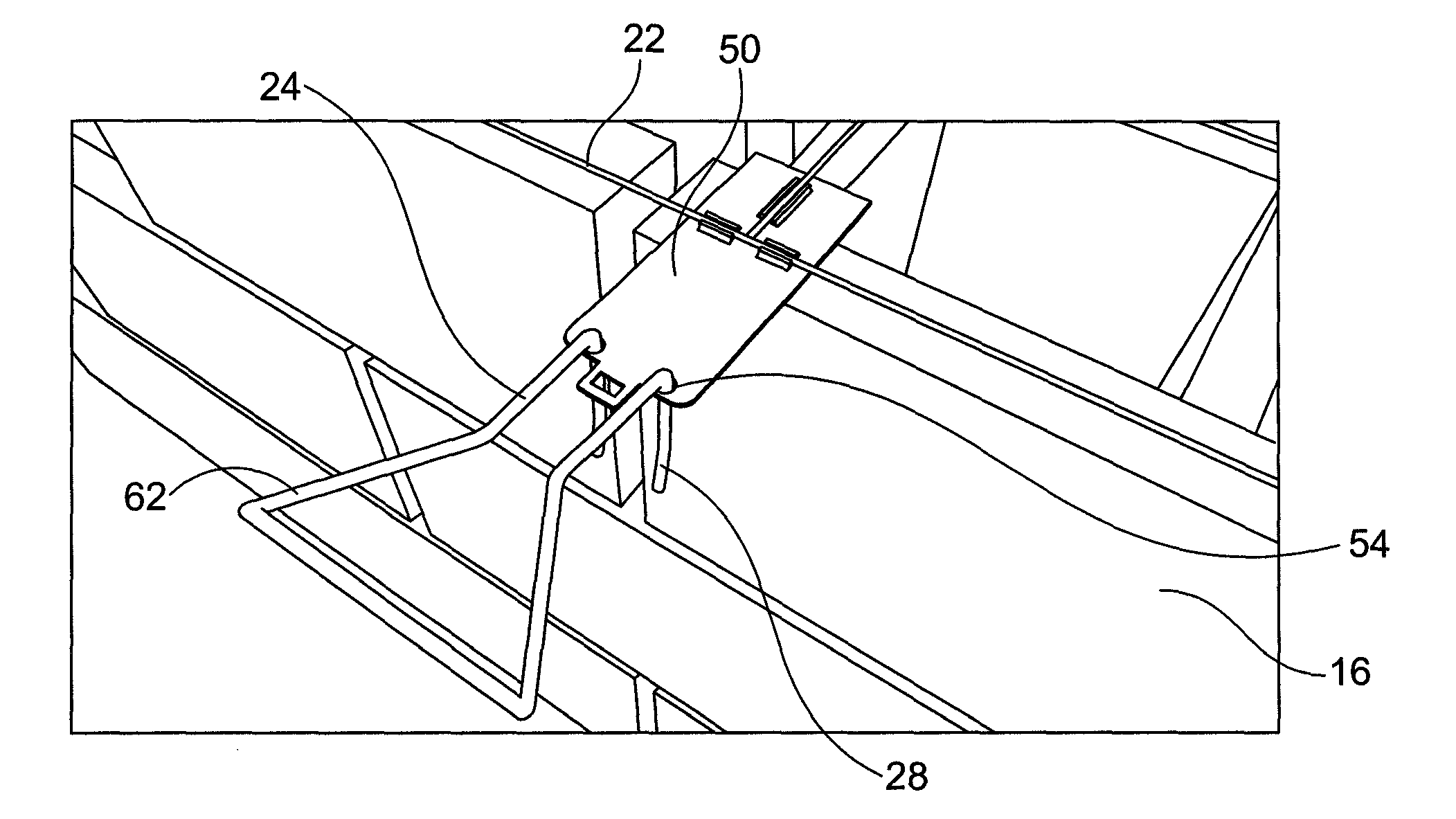
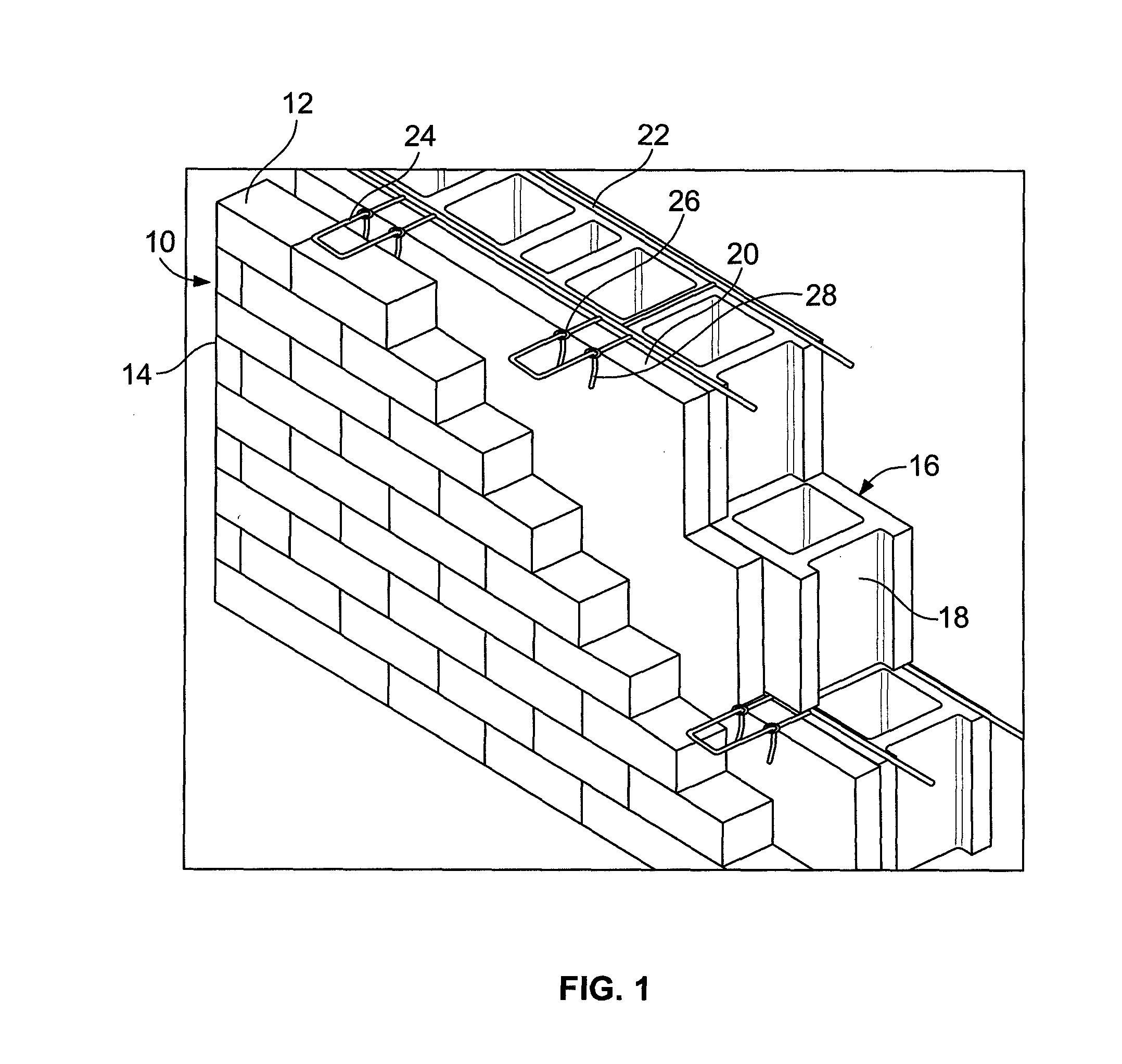
[0031]The present disclosure concerns a new and improved masonry wall wire reinforcement apparatus and system. The apparatus and system is intended to establish a positive lateral load connection between an outer veneer wall and an inner backup wall, otherwise known as a supportive wall. The veneer wall may be made up of aesthetic brick, while the inner wall may be made up of Concrete Masonry Units or CMU. The present invention generally includes a masonry wall wire reinforcement product or wire reinforcement, along with a clip, or in some cases multiple clips, and a pintle or wire tie.

[0032]In general use and as disclosed in detail herein, the present invention allows for the clip to be attached to the masonry wall wire reinforcement product, which is placed in between the layers of bricks of the backup wall. The clips are configured to extend out from the backup wall and allow for a pintle tie to be inserted into the openings of the clip. The veneer wall can then be built with the...


PUM


Abstract

A masonry wire reinforcement apparatus and system is disclosed for anchoring a veneer wall to a backup wall of Concrete Masonry Units using a masonry wire reinforcement product embedded into an inner support wall, along with clips and pintle ties, such that the clip is attached to the masonry wire reinforcement product and is configured to receive the pintle tie, which then is attached to the veneer wall. Also disclosed is a thermal attachment that can be attached to the clip and accept the pintle tie thereby reducing the transfer of energy from the outer veneer wall to the inner support wall.

Description

PRIORITY STATEMENT[0001]This application claims the benefit of U.S. Provisional Application No. 61 / 768,971, filed Feb. 25, 2013.FIELD OF THE INVENTION[0002]The present invention relates generally to a masonry wall wire reinforcement apparatus and system for anchoring a veneer wall to a backup wall of Concrete Masonry Units and, more specifically, the present invention relates generally to a system and apparatus for connecting a veneer wall to a backup wall using wire ladder or truss type reinforcement along with a clip that can be attached to the wire reinforcement and can be configured to receive the pintle tie, which then is embedded in the veneer wall. Further, an optional thermal attachment is available to be placed between the pintle tie and the clip to reduce thermal transfer.BACKGROUND OF THE INVENTION[0003]In many cases, construction of a wall of a building includes a backup wall made up of numerous cinder or concrete blocks, otherwise known as, Concrete Masonry Units (CMU) ...

Claims


Application Information

Patent Timeline
Patent Type & Authority Patents(United States)
IPC IPC(8): E04B1/02E04C3/30E04B1/41E04B2/02E04B2/44E04B2/56
CPCE04B1/4185E04B2/44E04B2002/565E04B2002/0256
Inventor CURTIS, PAULSANCHEZ, DAVID
Owner MECHANICAL PLASTICS CORP
Why Eureka
Try Eureka