Liquid cooled thermosiphon with flexible coolant tubes

Active Publication Date: 2006-07-18
COOLIT SYSTEMS INC
View PDF22 Cites 56 Cited by
  • Summary
  • Abstract
  • Description
  • Claims
  • Application Information

AI Technical Summary

Benefits of technology

[0014]The heat transfer rate of the two-phase secondary fluid is inherently higher than that of the single-phase working fluid. Therefore, besides enhancing the cooling capacity of the TCU, the invention solves the problem of corrosion

Problems solved by technology

However, these electronic devices are increasingly being miniaturized and designed to achieve increase

Method used


Image

  • Liquid cooled thermosiphon with flexible coolant tubes
  • Liquid cooled thermosiphon with flexible coolant tubes
  • Liquid cooled thermosiphon with flexible coolant tubes

Examples


Embodiment Construction

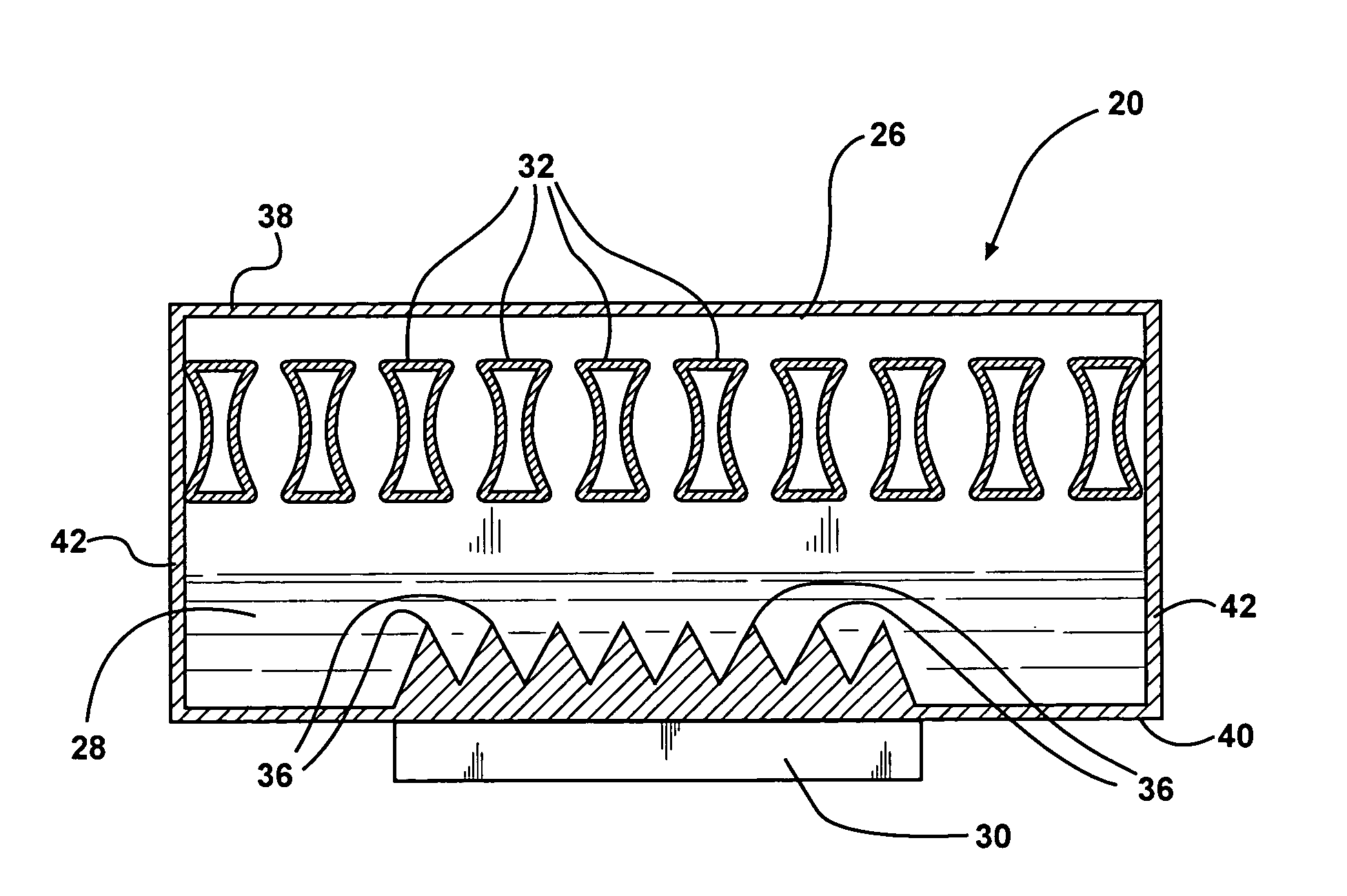
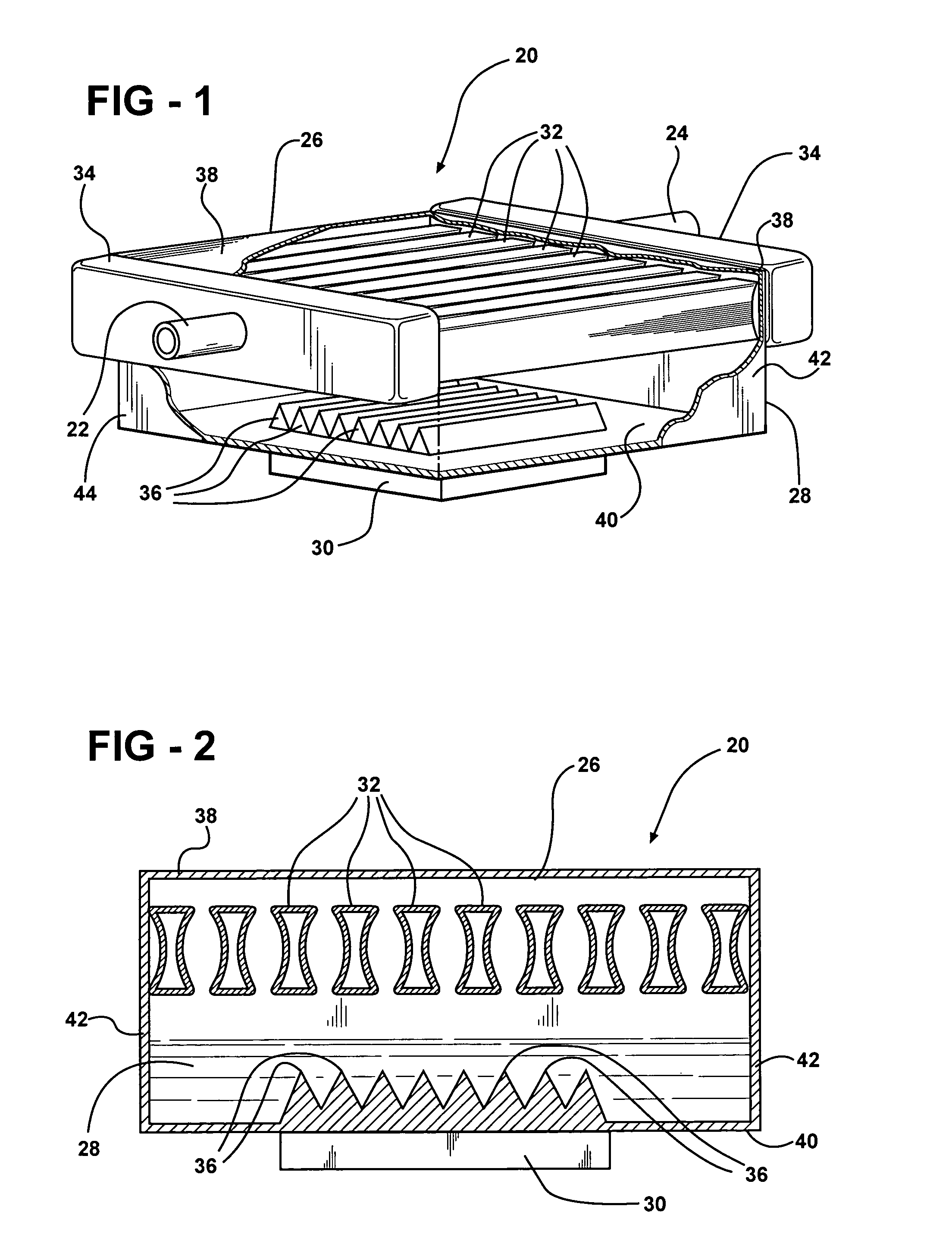
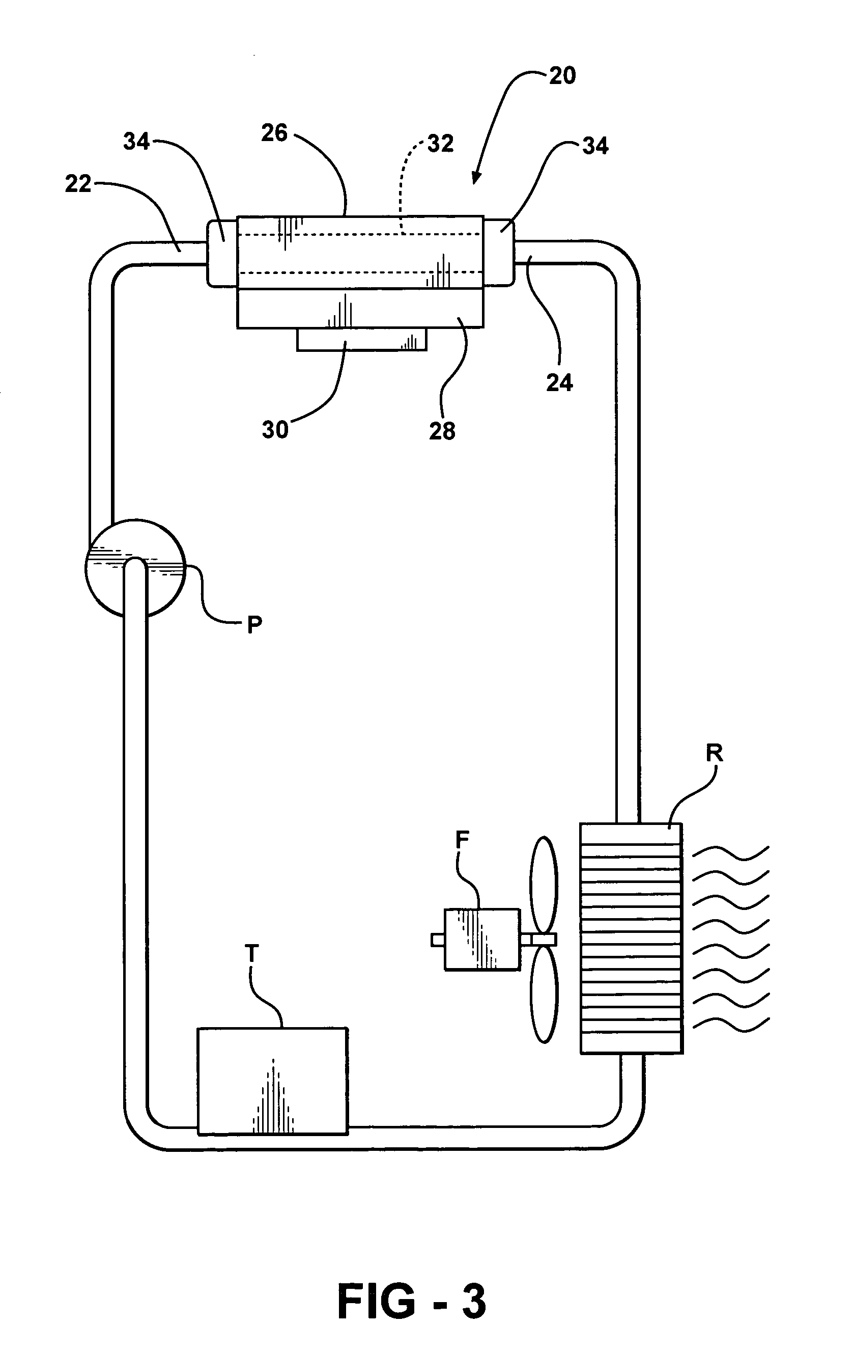
[0019]A fluid heat exchanger comprises a housing 20 having an inlet 22 and an outlet 24 and an upper portion 26 and a lower portion 28 extending between the inlet 22 and the outlet 24 for establishing a direction of flow from the inlet 22 to the outlet 24. The assembly is used to cool an electronic device 30 engaging or secured to the lower portion 28 of the housing 20, as by being adhesively held in a recess (not shown) in the bottom of the housing 20.

[0020]A plurality of tubes 32 extend between a pair of header tanks 34 in fluid communication with the inlet 22 and the outlet 24 for establishing a flow of coolant liquid from the inlet 22 to the outlet 24 in the upper portion 26 of the housing 20. The inlet 22 and outlet 24 header tanks 34 are in fluid communication with opposite ends of the tubes 32 for feeding coolant liquid to the various tubes 32 from the inlet 22 and for collecting coolant liquid from the various tubes 32 for feeding the coolant liquid to the outlet 24. In othe...


PUM


Abstract

A fluid heat exchanger assembly cools an electronic device with a cooling fluid supplied from a heat extractor (R, F) to a plurality of tubes extending between header tanks in an upper portion of a housing. A refrigerant is disposed in the lower portion of the housing for liquid-to-vapor transformation. The tubes are radially flexible to vary the volume of the tubes for modulating the flow of coolant liquid through the tubes in response to heat transferred by an electronic device to the lower portion of the housing.

Description

RELATED APPLICATIONS[0001]The subject invention is related to the inventions disclosed in co-pending applications DP-311409 (H&H 60408-566) and DP-312789 (H&H 60408-597), filed concurrently herewith.BACKGROUND OF THE INVENTION[0002]1. Field of the Invention[0003]A fluid heat exchanger assembly for cooling an electronic device.[0004]2. Description of the Prior Art[0005]Research activities have focused on developing assemblies to efficiently dissipate heat from electronic devices that are highly concentrated heat sources, such as microprocessors and computer chips. These electronic devices typically have power densities in the range of about 5 to 35 W / cm2 and relatively small available space for placement of fans, heat exchangers, heat sink assemblies and the like. However, these electronic devices are increasingly being miniaturized and designed to achieve increased computing speeds that generate heat up to 200 W / cm2.[0006]Heat exchangers and heat sink assemblies have been used that ...

Claims


Application Information

Patent Timeline
IPC IPC(8): F28D15/00F28F7/00
CPCF28D15/00F28D15/0233F28F3/02F28F13/00H01L23/473H01L2924/0002H01L2924/00
Inventor REYZIN, ILYABHATTI, MOHINDER SINGH
Owner COOLIT SYSTEMS INC
Why Eureka
Try Eureka