Refrigeration device

A refrigeration device and cooling capacity technology, which is applied to household refrigeration devices, cooling fluid circulation devices, refrigerators, etc., and can solve problems such as energy consumption

Active Publication Date: 2009-10-28
DAIKIN IND LTD
View PDF1 Cites 8 Cited by
  • Summary
  • Abstract
  • Description
  • Claims
  • Application Information

AI Technical Summary

Problems solved by technology

However, in the conventional refrigerating apparatus, even in the above-mentione

Method used


Image

  • Refrigeration device
  • Refrigeration device
  • Refrigeration device

Examples


no. 1 approach

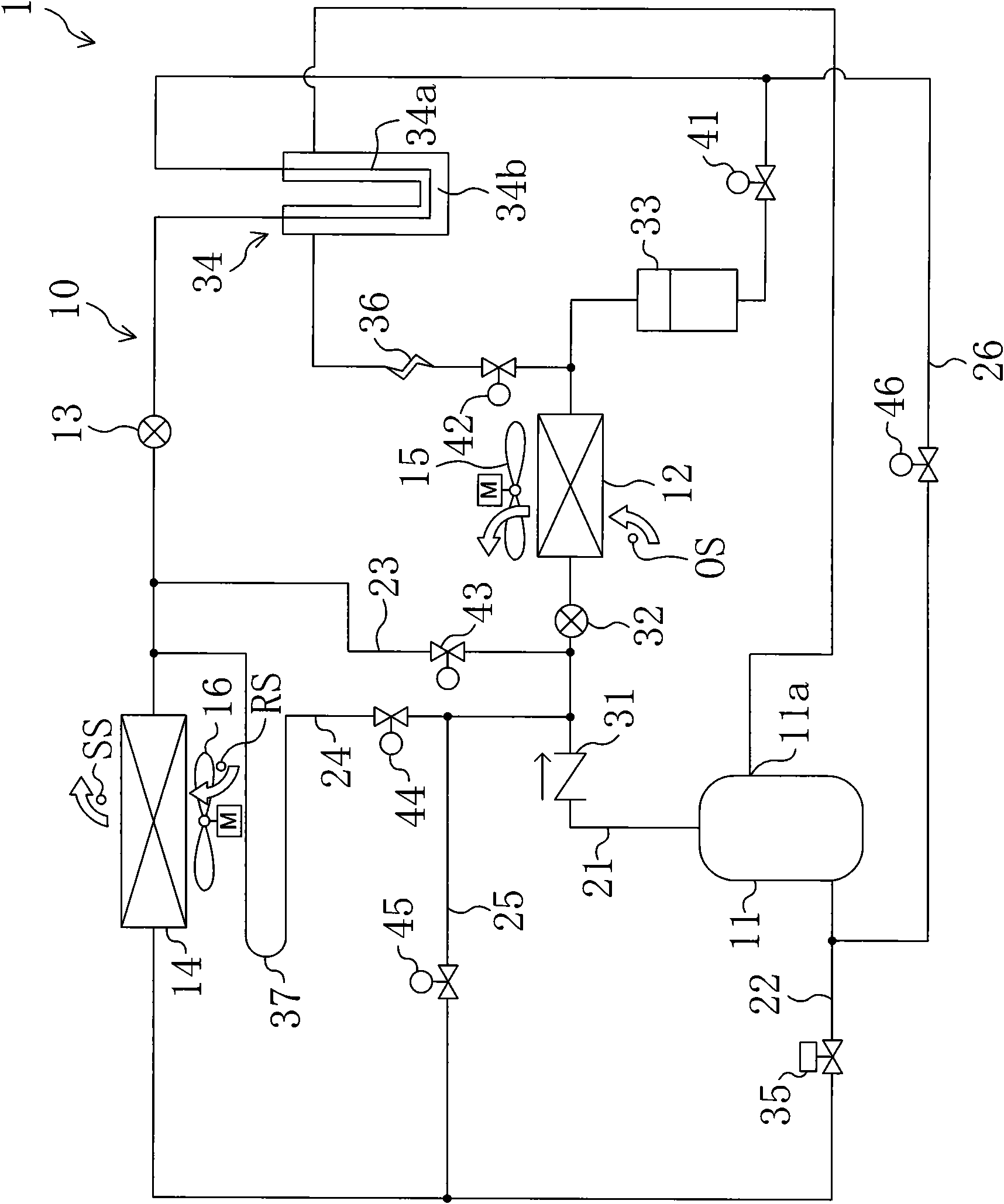
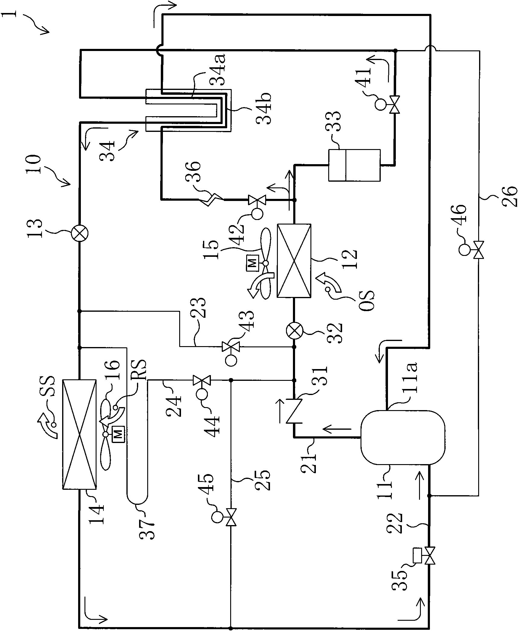
A first embodiment of the present invention will be described. Such as figure 1 As shown, the refrigeration apparatus 1 of this embodiment is an apparatus which cools the interior of the container used for sea transportation etc. FIG. This refrigerating apparatus 1 includes a refrigerant circuit 10 , an external fan 15 , and an internal fan 16 , and the refrigerant circuit 10 circulates a refrigerant to perform a vapor compression refrigeration cycle.

[0049] In the refrigerant circuit 10, a compressor 11, a condenser 12, an expansion valve 13, and an evaporator 14 are provided as main components.

[0050] The compressor 11 is constituted by a fixed capacity type scroll compressor in which the rotation speed of a compressor motor is constant.

[0051] The condenser 12 is arranged outside the refrigerator, and constitutes a so-called air-cooled condenser. The outdoor fan 15 is provided near the condenser 12 . The outside fan 15 sends outside air (outside air) to the condens...

no. 2 approach

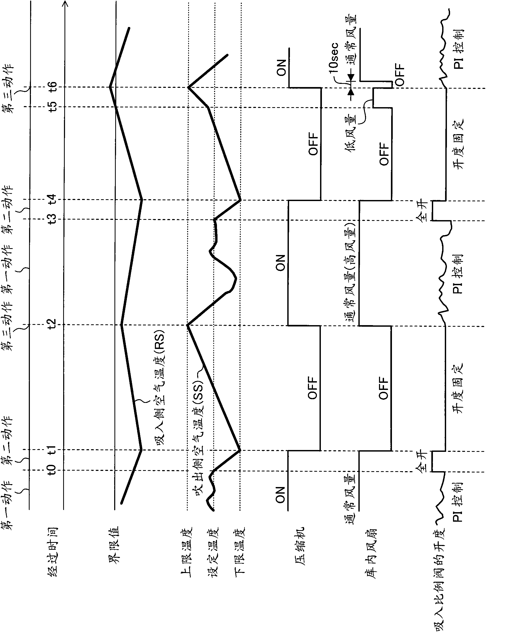
A second embodiment of the present invention will be described. Such as Figure 8 As shown, in the refrigerating apparatus 1 of the present embodiment, different lower limit temperatures of the outlet-side air temperature are set for the normal operation mode and the energy-saving operation mode in the first embodiment. In addition, points different from the first embodiment described above will be described here.

[0106] Specifically, in the normal operation mode of the present embodiment, the lower limit value of the target range of the outlet air temperature is set as the first lower limit temperature. On the other hand, in the energy-saving operation mode, the lower limit value of the target range of the outlet air temperature is set to a second lower limit temperature lower than the first lower limit temperature. That is, in the present embodiment, the lower limit value of the target range of the outlet air temperature in the energy-saving operation mode is made lower t...

no. 3 approach

A third embodiment of the present invention will be described. Although not shown, in the refrigeration system 1 of this embodiment, in the energy-saving operation mode of the first embodiment described above, the set temperature of the outlet air temperature is lowered every time a predetermined operation time elapses. In addition, at this time, the upper limit temperature and the lower limit temperature of the target range of the outlet air temperature do not change. In addition, points different from the first embodiment described above will be described here.

[0110] Specifically, the set temperature of the outlet-side air temperature is maintained at the initial value until a predetermined time (for example, one hour) elapses from the start of operation in the energy-saving operation mode. Then, when a predetermined time elapses from the start of the operation, the controller lowers the set temperature of the outlet air temperature by a certain amount (for example, 0.1° ...


PUM


Abstract

The invention discloses a refrigeration device. The refrigeration system has an energy saving operation mode performing: a first action in which a compressor (11) and an internal fan (16) are driven while the cooling capacity of an evaporator (14) is regulated; a second action in which, when the blow-off-side air temperature in a cold storage is kept at a set value in the first action, the cooling capacity of the evaporator (14) is increased to lower the blow-off-side air temperature to a lower limit temperature of a desired temperature range containing the set value and the compressor (11) and the internal fan (16) are then stopped; and a third action in which, when the blow-off-side air temperature after the second action rises to an upper limit temperature of the desired temperature range, the first action is restarted. Furthermore, the energy saving operation mode is configured so that when the suction-side air temperature in the cold storage after the second action rises to a limit value, the internal fan (16) is activated at a lower air flow rate than in the first action.

Description

technical field [0001] The present invention relates to a refrigeration device provided with a cooling heat exchanger for cooling the inside of a refrigerator, and more particularly to an energy-saving operation method. Background technique [0002] Conventionally, freezers for cooling the interior of refrigerators, freezers, and the like have been known. [0003] For example, Patent Document 1 discloses a refrigeration device that cools the interior of containers used for marine transportation and the like. This refrigeration system includes a refrigerant circuit in which a compressor, a condenser, an expansion valve, and a cooling heat exchanger (evaporator) are connected. In the refrigerant circuit of this refrigerating apparatus, a refrigerant is circulated to perform a vapor compression refrigeration cycle. As a result, the refrigerant flowing through the cooling heat exchanger absorbs heat from the interior air and evaporates, thereby cooling the interior air. In th...

Claims


Application Information

Patent Timeline
IPC IPC(8): F25D11/00F25B1/00F25D17/06
CPCF25B2400/13Y02B40/32Y02B30/743F25D11/00F25B2600/112F25B2600/0251F25B2400/051F25D29/00Y02B30/70Y02B40/00
Inventor 田中滋人
Owner DAIKIN IND LTD
Why Eureka
Try Eureka