Thermoconditional suit achieving cooling and heating

A dual-purpose, temperature-adjusting technology, applied in clothing, applications, clothing, etc., can solve the problems that the gas-liquid separator needs to be carried together on the body, the body of the wearer is unevenly cooled, and the separation rate of cold and hot gases can be reduced. , to achieve the effect of improving energy separation performance, increasing the convenience of use, and increasing the cooling capacity

Inactive Publication Date: 2015-09-09
JIANGSU HAOJIAHUO TECH
View PDF0 Cites 8 Cited by
  • Summary
  • Abstract
  • Description
  • Claims
  • Application Information

AI Technical Summary

Problems solved by technology

[0005] The vortex tube used for the separation of hot and cold gases used in existing temperature control clothing usually adopts a single-channel vortex tube, and its inlet section is composed of a straight tube and a circular channel with equal cross-section. The compressed gas enters through the straight tube and the circular channel successively. For the nozzle, because the flow section changes suddenly before and after the connection between the straight pipe and the circular channel, the separation of the air flow is caused, resulting in flow loss. At the same time, the cross-sectional area of ​​the circular ring is equal. There is a large change in the airflow velocity, resulting in local vortices

Method used


Image

  • Thermoconditional suit achieving cooling and heating
  • Thermoconditional suit achieving cooling and heating
  • Thermoconditional suit achieving cooling and heating

Examples


Example Embodiment

[0022] Example

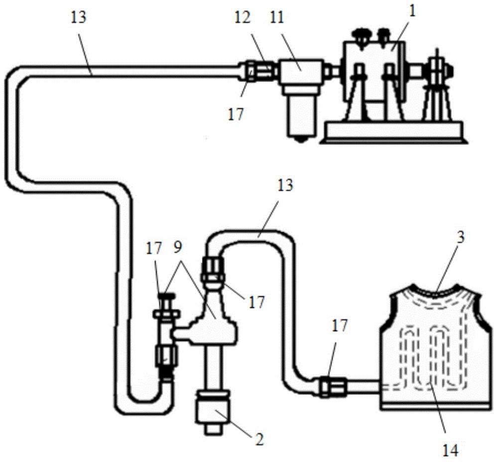
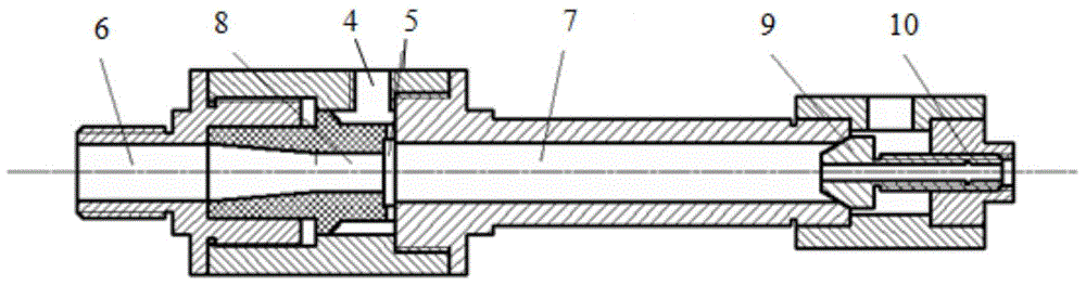
[0023] as attached figure 1 As shown, the side wall of the double-way vortex tube 2 is provided with an air inlet nozzle 4, and the tangential direction edge of the air inlet nozzle 4 is a vortex chamber 5, and one side of the vortex chamber 5 is a cold end pipe 6, and the other side is a hot end pipe 7, and the cold end pipe 7 is formed on the other side of the vortex chamber 5. The end pipe 6 and the hot end pipe 7 are respectively connected with mufflers, the separation orifice 8 is located between the cold end pipe 6 and the vortex chamber 5, the hot end pipe 7 is equipped with a hot end regulating valve 9, and the center of the hot end regulating valve 9 is set There is an additional circuit 10, which can make the feedback gas enter the double-way vortex tube 2, the temperature of the feedback gas is equal to the inlet temperature, and the pressure is relatively small. The experimental results show that the double-way vortex tube with this structure can i...


PUM


Abstract

The invention discloses a thermoconditional suit achieving cooling and heating, and belongs to the technical field of labor protection clothing. The thermoconditional suit achieving cooling and heating comprises an air compressor, a double-circuit vortex tube and a thermoconditional suit body. An air inlet nozzle is formed in one side wall of the double-circuit vortex tube, a vortex chamber is arranged on the edge in the tangential direction of the air inlet nozzle, a cold end tube is arranged on one side of the vortex chamber, and a hot end tube is arranged on the other side of the vortex chamber. A separating pore plate is located between the cold end tube and the vortex chamber, a hot end regulating valve is arranged at one end of the hot end tube, and an additional loop is arranged in the center of the hot end regulating valve. The air compressor is directly connected with a gas-liquid separator, the gas-liquid separator is connected with a dryer, the dryer is connected the hot end regulating valve through a hose and then connected with the double-circuit vortex tube, and the hot end tube of the double-circuit vortex tube is connected with an exhaust guide pipe in the thermoconditional suit body. The thermoconditional suit is ingenious in design, safe to use, easy to operate, quite convenient to carry, easy to clean, low in cost and capable of meeting use needs, and a good work effect is achieved.

Description

technical field [0001] The invention belongs to the technical field of labor protection clothing manufacturing, and in particular relates to a dual-purpose temperature-regulating clothing for cold and heat. Background technique [0002] Among the many occupations, the staff of many positions often have to face the working environment of high temperature or severe cold. When engaged in physical labor outdoors in summer or in other high-temperature environments, the physical energy consumption of the human body is very large, and it is particularly prone to fatigue and low work efficiency; when it is outdoors in winter or in other severe cold conditions, body heat is quickly lost during labor , which leads to hypothermia of the human body, making it easy to catch colds, frostbite and other diseases. [0003] Vortex tube (VORTEX TUBE), also known as vortex tube. When the compressed gas enters the vortex tube, it flows to one side in a high-speed rotation. During the movement ...

Claims


Application Information

Patent Timeline
IPC IPC(8): F25B9/04F25B41/00A41D13/005F25B41/20
CPCA41D13/005F25B9/04F25B41/40
Inventor 袁在良
Owner JIANGSU HAOJIAHUO TECH
Why Eureka
Try Eureka