
Imaging lens capable of blocking stray light

a technology of stray light and imaging lens, which is applied in the direction of camera filters, instruments, mountings, etc., can solve the problems of ineffective blocking of stray light at large incident angles, adverse effect on image quality, and conventional light shielding components

Inactive Publication Date: 2015-03-24
GENIUS ELECTRONICS OPTICAL CO LTD
View PDF2 Cites 10 Cited by
  • Summary
  • Abstract
  • Description
  • Claims
  • Application Information

AI Technical Summary

Benefits of technology

The present invention aims to provide an imaging lens that can prevent unwanted light from entering the system and overcome the shortcomings of existing technology.

Problems solved by technology

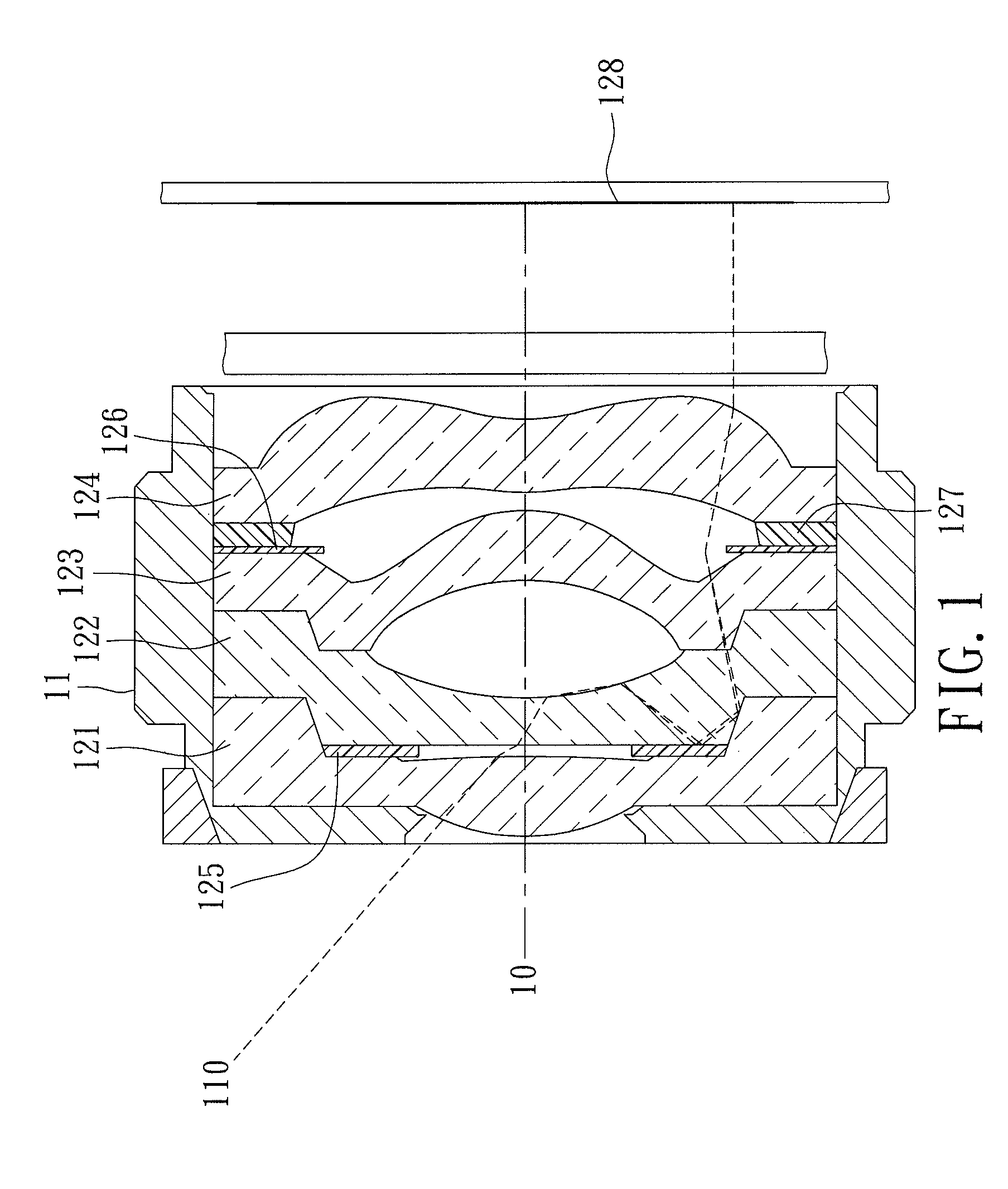
However, the conventional light shielding components 125, 126 do not effectively block stray light at large incident angles.
As shown in FIG. 1, stray light 110 can still arrive at an imaging plane 128 after reflection and refraction among the lens components 121˜124 in the lens barrel 11, resulting in adverse effect on image quality.
This causes the conventional light shielding components 125, 126 which are extremely thin to deform easily and to be difficult to be attached evenly to the lens components 121˜124.
Such drawbacks affect the precision in the assembly of the conventional imaging lens, adversely affecting the light shielding effect and the image quality.
Therefore, such conventional imaging lens has components that are difficult to manufacture, a large number of components that affects precision in assembly, and the image quality problems due to the adverse effect on precision in assembly.

Method used


Image

  • Imaging lens capable of blocking stray light
  • Imaging lens capable of blocking stray light
  • Imaging lens capable of blocking stray light

Examples


Embodiment Construction

[0024]Before the present invention is described in greater detail, it should be noted that like elements are denoted by the same reference numerals throughout the disclosure.

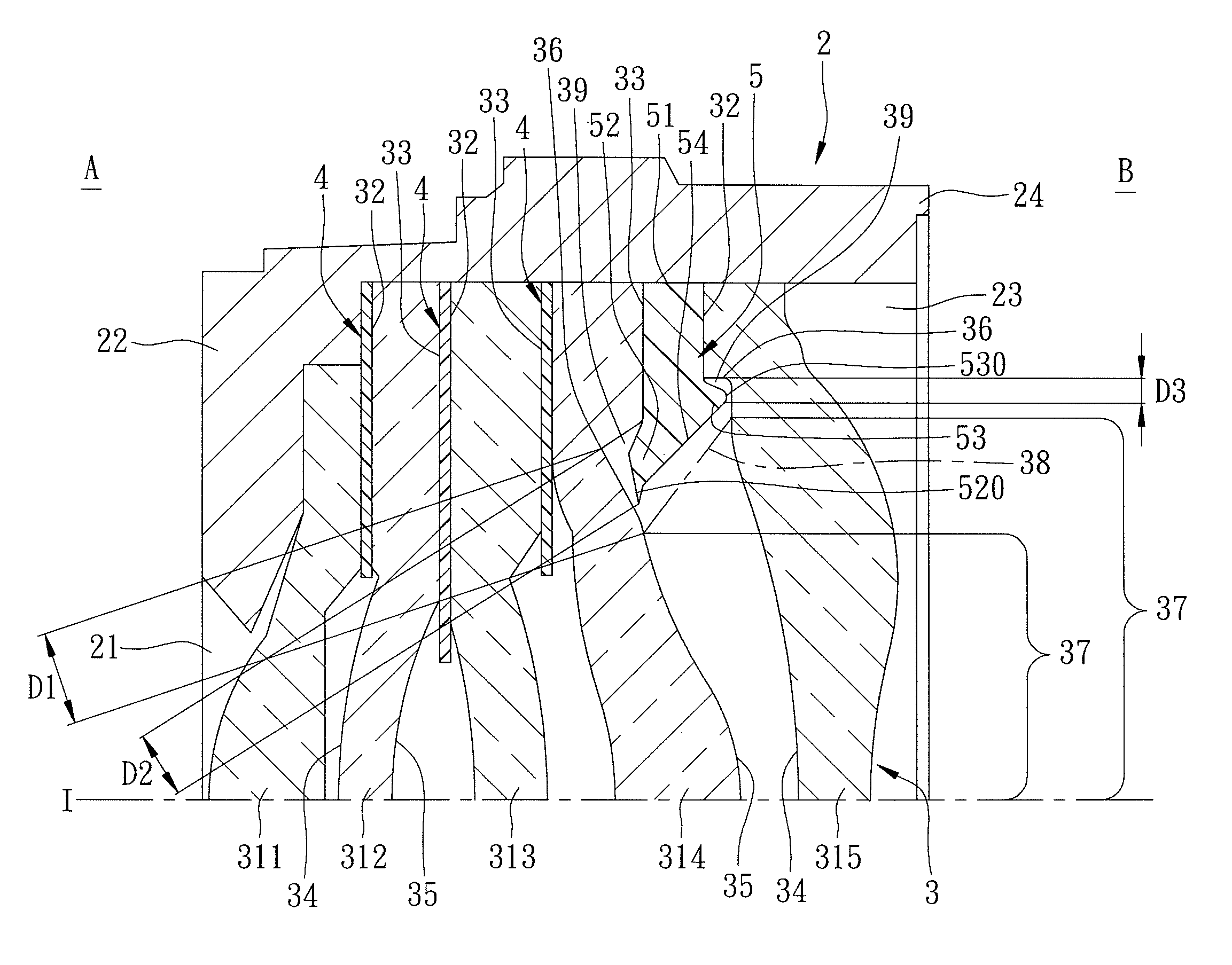
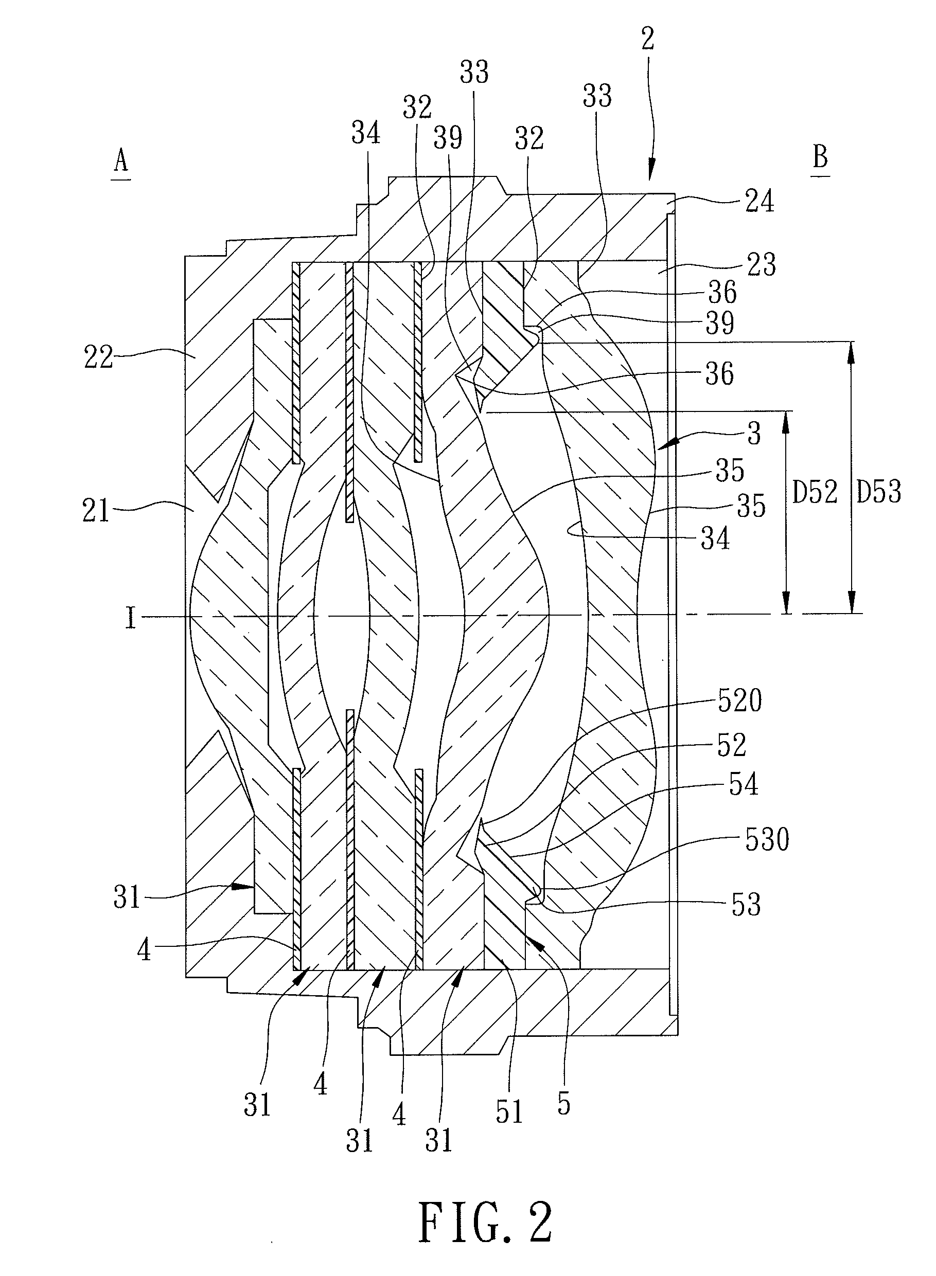
[0025]Referring to FIGS. 2, 3 and 4, a first preferred embodiment of the imaging lens 2 according to this invention is shown to include a lens barrel 2, an imaging unit 3 disposed in the lens barrel 2, a plurality of light shielding plates 4, and a light shielding unit 5.

[0026]The lens barrel 2 includes abase wall 22 formed with a light incident hole 21 at an optical axis (I) of the imaging lens 2 and disposed proximate to an object side (A), and a surrounding wall 24 that extends from an outer periphery of the base wall 22 toward an image side (B), and that cooperates with the base wall 22 to define a receiving space 23.

[0027]The imaging unit 3 is disposed in the receiving space 23 of the lens barrel 2, and includes a plurality of imaging components 31 arranged along the optical axis (I). Each of the imaging co...


PUM


Abstract

An imaging lens includes a lens barrel, an imaging unit and a light shielding unit. The lens barrel includes a base wall formed with a light incident hole at an optical axis of the imaging lens and a surrounding wall that extends from and cooperates with the base wall to define a receiving space. The imaging unit includes a plurality of imaging components each having an annular front contact surface and an annular back contact surface. The light shielding unit includes an annular retaining portion clamped between an adjacent pair of the imaging components, an object-side protruding portion with a first edge, and an image-side protruding portion with a second edge.

Description

CROSS-REFERENCE TO RELATED APPLICATION[0001]This application claims priority of Chinese application no. 201210518752.8, filed on Dec. 6, 2012, the contents of which are hereby incorporated by reference in their entirety for all purposes.BACKGROUND OF THE INVENTION[0002]1. Field of the Invention[0003]The present invention relates to an imaging lens capable of blocking stray light.[0004]2. Description of the Related Art[0005]Referring to FIG. 1, a conventional imaging lens includes a lens barrel 11, lens components 121-124 disposed in the lens barrel 11 along an optical axis 10, two light shielding components 125, 126 disposed between the lens components 121, 122, and between the lens components 123, 124, respectively, and a washer 127 clamped between the light shielding component 126 and the lens component 124. The light shielding components 125, 126 are disposed to block stray light for preventing degradation of image quality. The washer 127 serves to reduce the thickness of a mount...

Claims


Application Information

Patent Timeline
Patent Type & Authority Patents(United States)
IPC IPC(8): G03B11/04G02B13/00G02B7/00G02B7/02G02B27/00
CPCG02B27/0018G02B13/0035G02B7/02G02B7/022G02B13/004G02B13/0045
Inventor CHO, HUNG-CHANGDENG, YI-MANXUE, LING-HUI
Owner GENIUS ELECTRONICS OPTICAL CO LTD
Learn More