Safety device, closing device and evaluation unit

a technology of safety devices and closing devices, applied in the direction of frequency-division multiplexes, door/window protection devices, instruments, etc., can solve the problems of objects being caught or trapped by the movement elemen

Active Publication Date: 2015-03-24
CEDES AG
View PDF19 Cites 5 Cited by
  • Summary
  • Abstract
  • Description
  • Claims
  • Application Information

AI Technical Summary

Benefits of technology

[0007]In principle, the safety device according to the invention serves for avoiding undesired collisions during the movement of the movement element. If the movement element, for instance a gate, is closed, it can happen, for example, that a person, an article or some other object enters the movement space of the movement element. Without any safety device, in principle in such a case the object could be caught or trapped by the movement element. Such accidents are intended to be able to be avoided.
[0049]In one preferred development of the invention, the sensors can be arranged parallel to the direction of movement of the movement element, furthermore in particular such that they lie in the movement plane of the movement element. The parallel arrangement along the direction of movement makes it possible for one sensor after the other successively to be able to detect the moving movement element. The arrangement in the movement plane makes it possible for the movement space in which there could be a risk of collision to be monitored as completely as possible.

Problems solved by technology

Without any safety device, in principle in such a case the object could be caught or trapped by the movement element.

Method used


Image

  • Safety device, closing device and evaluation unit
  • Safety device, closing device and evaluation unit
  • Safety device, closing device and evaluation unit

Examples


case i (cf.columns 3-4 in fig.2)

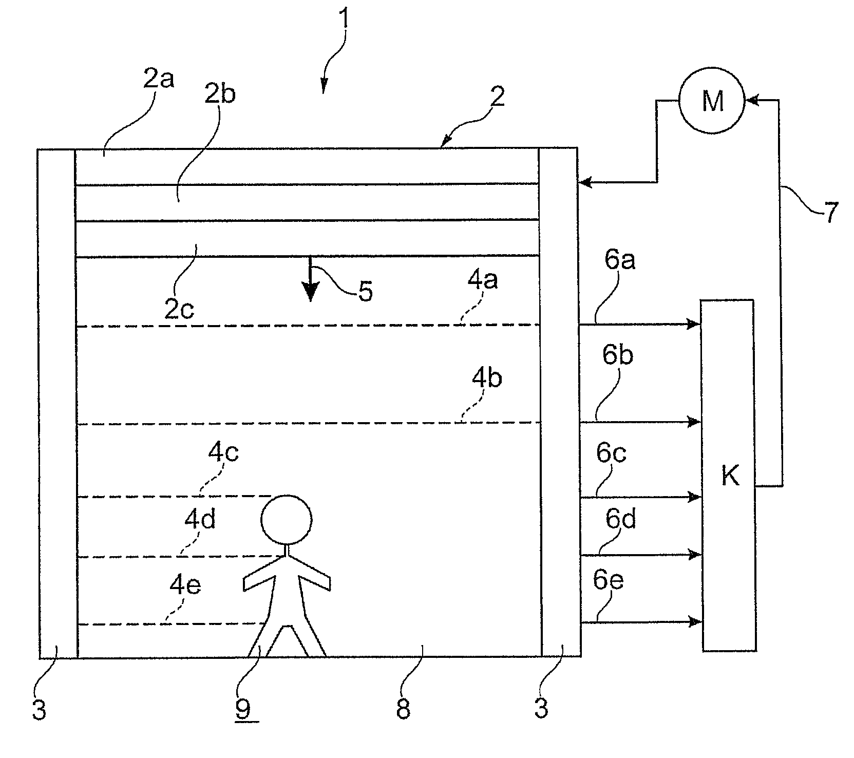
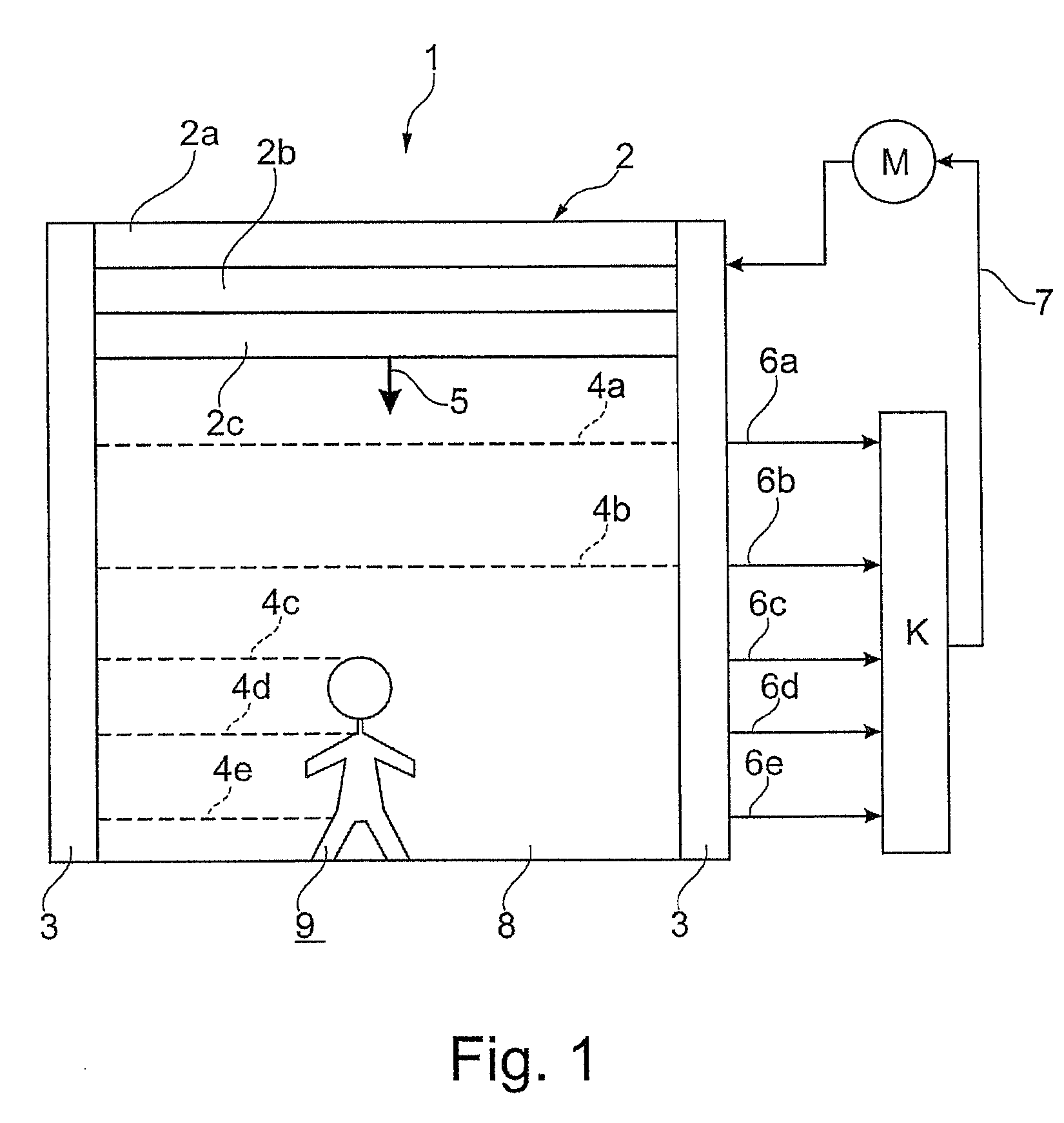
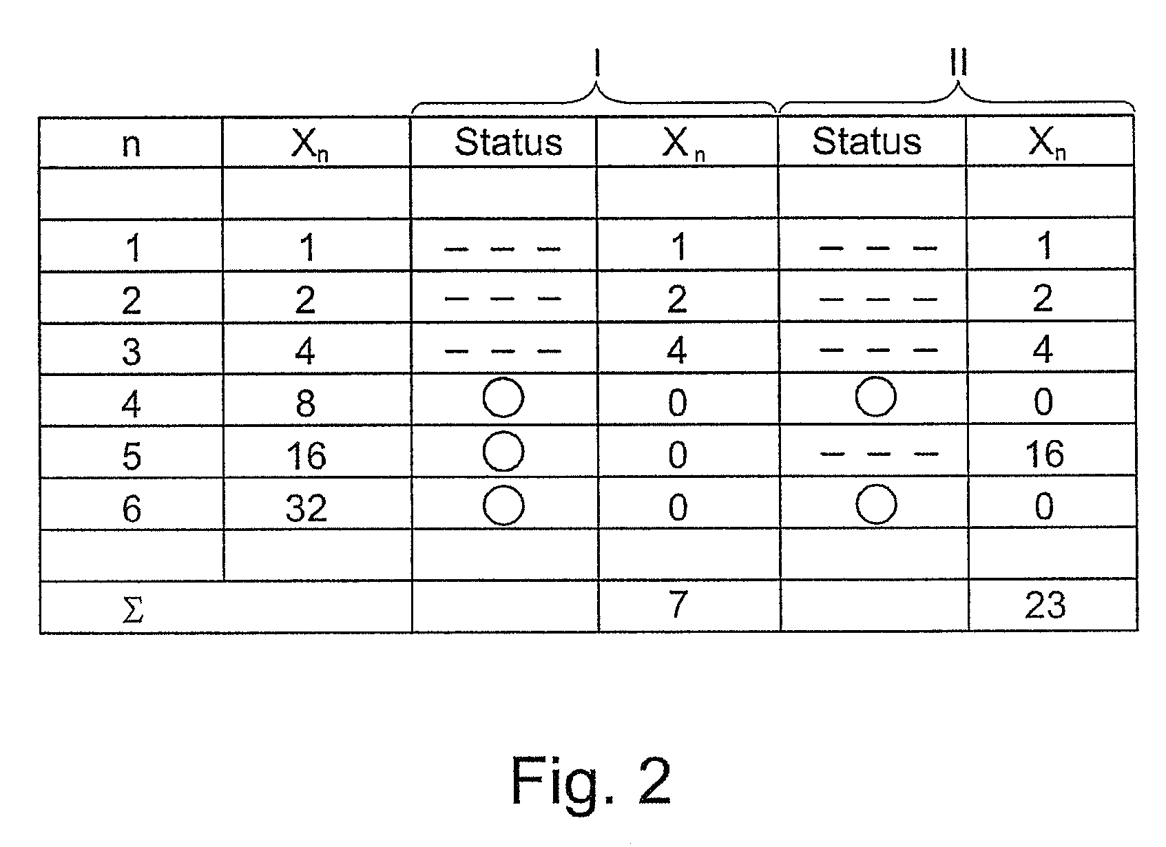
[0063]Case I (cf. columns 3-4 in FIG. 2): three light barriers are interrupted; in the present case, the first light barrier is assigned the value 1, the second light barrier is assigned the value 2, the third light barrier is assigned the value 4. The remaining light barriers are respectively assigned the value 0. Since, in the present exemplary embodiment, an addition is provided as mathematical operation, the value 7 arises as the result value (sum) in case I. The comparison table contains the value 7 since the comparison table contains all values which can be formed if in order 1 to a maximum of N light barriers is / are interrupted. The comparison table therefore contains the values 1, 3, 7, 15, 31, 63. The result value 7 means that the first three light barriers are interrupted.

case ii (cf.columns 5-6 in fig.2)

[0064]Case II (cf. columns 5-6 in FIG. 2): as a result of a different configuration, in particular a penetrated object, this value cannot arise in principle. Case II shows that the light barriers 1, 2, 3 and 5 are interrupted. This case II cannot correspond to a movement of the door because the door would otherwise have to have, in the region of the fourth light barrier, an interruption which would have to allow the light beam of the light barrier to pass. The interruption of the fifth light barrier is therefore effected by an object which can bring about a collision and, consequently, the supervisory unit must stop the movement of the door. From a mathematical point of view, the result value 23 arises, which is not contained in the comparison table. This value correspondingly leads to an interruption. Since this mapping is advantageously bijective, a corresponding state can unambiguously be assigned to the result values. The supervisory unit can therefore deduce therefrom whether o...

case i (in fig.3)

[0067]Case I (in FIG. 3): if the door is moved further, then until the instant t it also passes the fourth light barrier and therefore correctly assumes the value 15, which is likewise contained in the comparison table and is also provided for the instant t. The supervisory unit therefore recognizes that the door is moving downward.


PUM


Abstract

A safety device for safeguarding a movable, guided movement element against undesired collisions with an object situated on a movement path of the movement element, said device comprising at least two sensors for detecting the object and the movement element and for outputting signals depending on the detection, and also having an evaluation unit for evaluating signals of the sensors and for generating a switch-off signal on the basis of the evaluation. For improved recognition of a risk of collision, the evaluation unit is designed to acquire from the at least two sensors a currently detected state vector from a set of state vectors which unambiguously comprise all possible combinations of the signals of the sensors, and to generate the switch-off signal in the case of predetermined state vectors.

Description

FIELD OF THE INVENTION[0001]The invention relates to a safety device for safeguarding a movable, guided movement element against undesired collisions, a closing device, and an evaluation unit.BACKGROUND OF THE INVENTION[0002]A device for safeguarding a driven movement element is known from the prior art, for example from EP 1 841 942 B 1. In the case of the device, an electronic unit determines, from the time difference from the first to the second light barrier as a result of the triggering of these light barriers, a time at which a downstream, third light barrier would be registered, and switches the third light barrier into the measurement state in a timely fashion before this event occurs.[0003]The problem addressed by the invention is to propose a safety device and a closing device which make it possible in an improved manner to recognize a risk of collision during the movement of the movement element.SUMMARY OF THE INVENTION[0004]Advantageous embodiments and development of the...

Claims


Application Information

Patent Timeline
Patent Type & Authority Patents(United States)
IPC IPC(8): G08B1/00G08B23/00E06B3/00H01J40/14G08B13/18E05F15/00E06B9/68E06B9/88
CPCE06B9/88E06B2009/6827E06B2009/6836E05F2015/0052E05Y2900/00E05Y2900/106E05F2015/436
Inventor LEUTENEGGER, TOBIASFREEDMAN, STEVEN
Owner CEDES AG
Why Eureka
Try Eureka