Apparatus for simultaneously inspecting and cleaning fiber connector

a fiber connector and cleaning technology, applied in the field of fiber connector inspectors, can solve the problems of complex design of cleaning apparatus, failure of fiber optics communication system, failure of fiber optics components or failure of the entire fiber optics communication system,

Active Publication Date: 2015-03-24
LIGHTEL TECH
View PDF2 Cites 20 Cited by
  • Summary
  • Abstract
  • Description
  • Claims
  • Application Information

AI Technical Summary

Benefits of technology

[0017]The fiberscope of the present application allows a fiber connector to be inspected and cleaned simultaneously without having to repeatedly inserting and removing the fiber connector to and from the fiberscope, and without having to repeatedly move the microscope and cleaner in and out the working scene by turns.
[0025]The at least one air nozzle is disposed at an angle from the ferrule endface of the fiber connector to allow the cleaning air from the at least one air nozzle to spray sideways onto the ferrule endface (and the fiber endfaces embedded in the ferrule endface) of the fiber connector received in the connector holder. This way, after contacting the endfaces, the cleaning air will bounce off sideways out of the open access space between the connector holder and the front panel to avoid secondary contamination.

Problems solved by technology

Any defect, scratch or contamination on the endface of a fiber connector can cause failure of a fiber optics component or failure of the entire fiber optics communication system.
However, this cleaning apparatus has a complicated design and requires a special dispensing assembly for the cleaning.
Due to the limitations of the apparatus, the connector endface cannot be cleaned manually.

Method used


Image

  • Apparatus for simultaneously inspecting and cleaning fiber connector
  • Apparatus for simultaneously inspecting and cleaning fiber connector
  • Apparatus for simultaneously inspecting and cleaning fiber connector

Examples


Embodiment Construction

[0026]The present invention will be described in detail in view of the accompanying drawings.

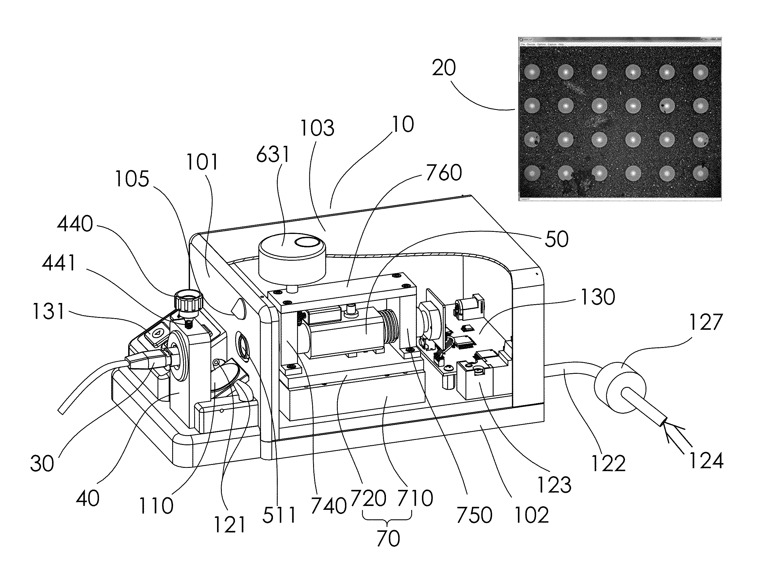
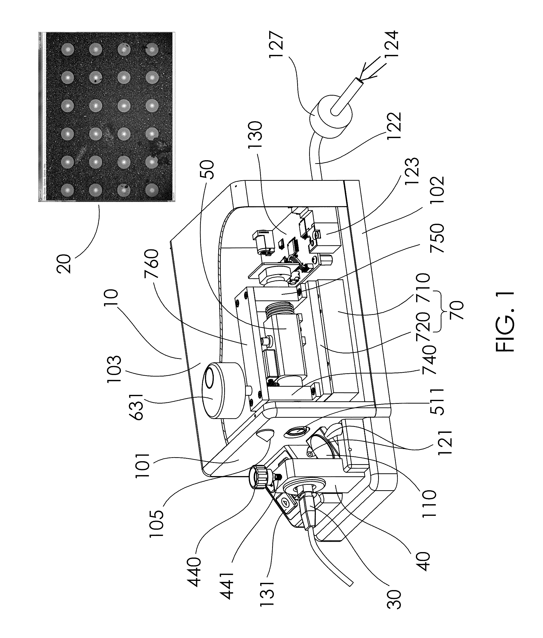
[0027]FIGS. 1-3 show a perspective cut-out view of an embodiment of the fiberscope 10 for simultaneously inspecting and cleaning a fiber connector according to the present invention. The fiberscope 10 allows an optical fiber connector to be inspected and cleaned simultaneously without the need to repeatedly insert and remove the connector.

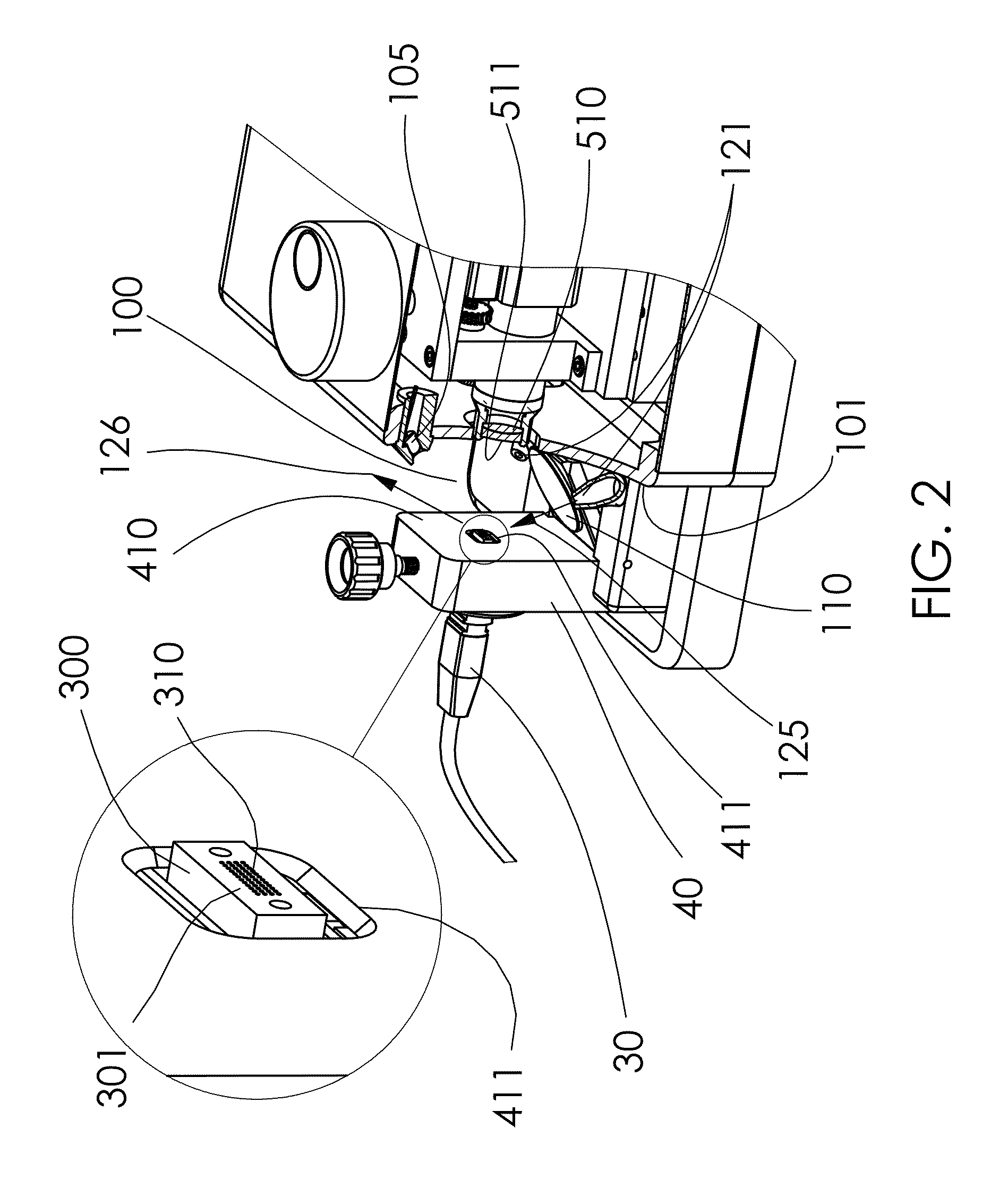
[0028]As illustrated in FIGS. 1-3, the fiberscope 10 according to the present invention includes a housing with a front panel 101, a top cover 103, and a base plate 102 connected to the lower portion of the front panel 101; a microscope system 50 disposed inside the housing; a connector holder 40 mounted on the base plate 102 at a certain distance in front of the front panel 101, thus defining an open access space 100 between the connector holder 40 and the front panel 101; a mirror 110 pivotally mounted in the open access space 100 between the connector ho...


PUM

PropertyMeasurementUnit
distanceaaaaaaaaaa
microscopeaaaaaaaaaa
angleaaaaaaaaaa

Abstract

The fiberscope for inspecting and cleaning a fiber connector simultaneously includes a housing with a front panel, a microscope system, a connector holder mounted at a distance from the front panel for receiving a connector ferrule of a fiber connector, and a translation stage for moving the microscope system transversely to align its optical axis with the connector ferrule. The fiberscope further includes a hand knob attached to a fine screw through the connector holder for adjusting the vertical position of the connector ferrule, a mirror pivotally mounted between the connector holder and the front panel, an LED lamp, air nozzles attached to the front panel, and a cleaning air tube for supplying compressed air to the air nozzles. The cleaning air from the air nozzles spray sideways onto the fiber endfaces so that the cleaning air bounces off sideways to avoid secondary contamination.

Description

CROSS REFERENCE TO RELATED APPLICATIONS[0001]This application claims the benefit of U.S. Provisional Application No. 61 / 789,910, filed Mar. 15, 2013, the entirety of which is incorporated by reference herein.BACKGROUND OF THE INVENTION[0002]1. Field of the Invention[0003]The invention relates to fiber connector inspectors and more particularly to an apparatus designed for simultaneously inspecting and cleaning the endface of the fiber connector.[0004]2. Description of the Related Art[0005]Fiber optics communication has been the dominant and widespread means for modern-day telecommunications. Fiber connectors are one of the key components of the fiber optics communication system. Any defect, scratch or contamination on the endface of a fiber connector can cause failure of a fiber optics component or failure of the entire fiber optics communication system. Therefore, it is important that the endface of every fiber connector be inspected, and cleaned when necessary, at both the manufac...

Claims


Application Information

Patent Timeline
Patent Type & Authority Patents(United States)
IPC IPC(8): G01N21/00B08B1/00B08B5/02G01M11/00G02B6/38
CPCG01M11/31B08B1/00B08B5/02G02B6/3866B08B2240/02
Inventor ZHOU, GEHUANG, SHANGYUANSHEN, PAI-SHENG
Owner LIGHTEL TECH
Why Eureka
Try Eureka