Fire pit that occupies a small space when disassembled

a fire pit and small space technology, applied in the field of fire pits, can solve the problems of affecting the quality of fire pits, difficult fire-starting, and haphazard activity of stacking logs, and achieve the effects of small space, and easy assembly and disassembly

Active Publication Date: 2015-03-31
MAU PAUL A
View PDF53 Cites 18 Cited by
  • Summary
  • Abstract
  • Description
  • Claims
  • Application Information

AI Technical Summary

Benefits of technology

[0019]The novel structure is easily assembled and disassembled. It occupies a small space when disassembled.
[0020]An important object of the invention is to provide a fire pit that is easily assembled and disassemble...

Problems solved by technology

For example, the ground may be wet, making fire-starting difficult.
Stacking the logs can also be a haphazard activity that does not result in well-ordered logs.
Accordingly, oxygen may not flow into the fire in an optimal manner.
The known fire pits lack means for arrangin...

Method used


Image

  • Fire pit that occupies a small space when disassembled
  • Fire pit that occupies a small space when disassembled
  • Fire pit that occupies a small space when disassembled

Examples


first embodiment

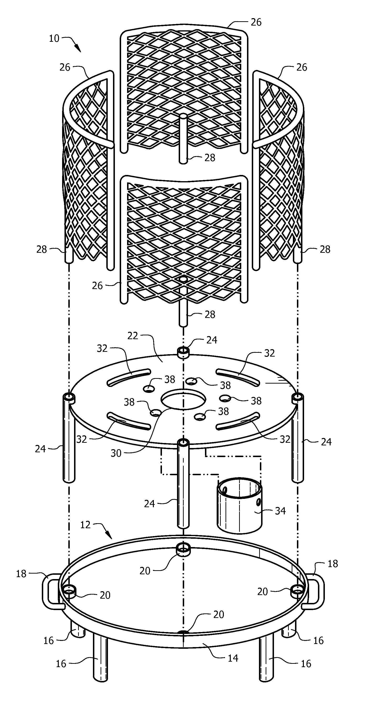
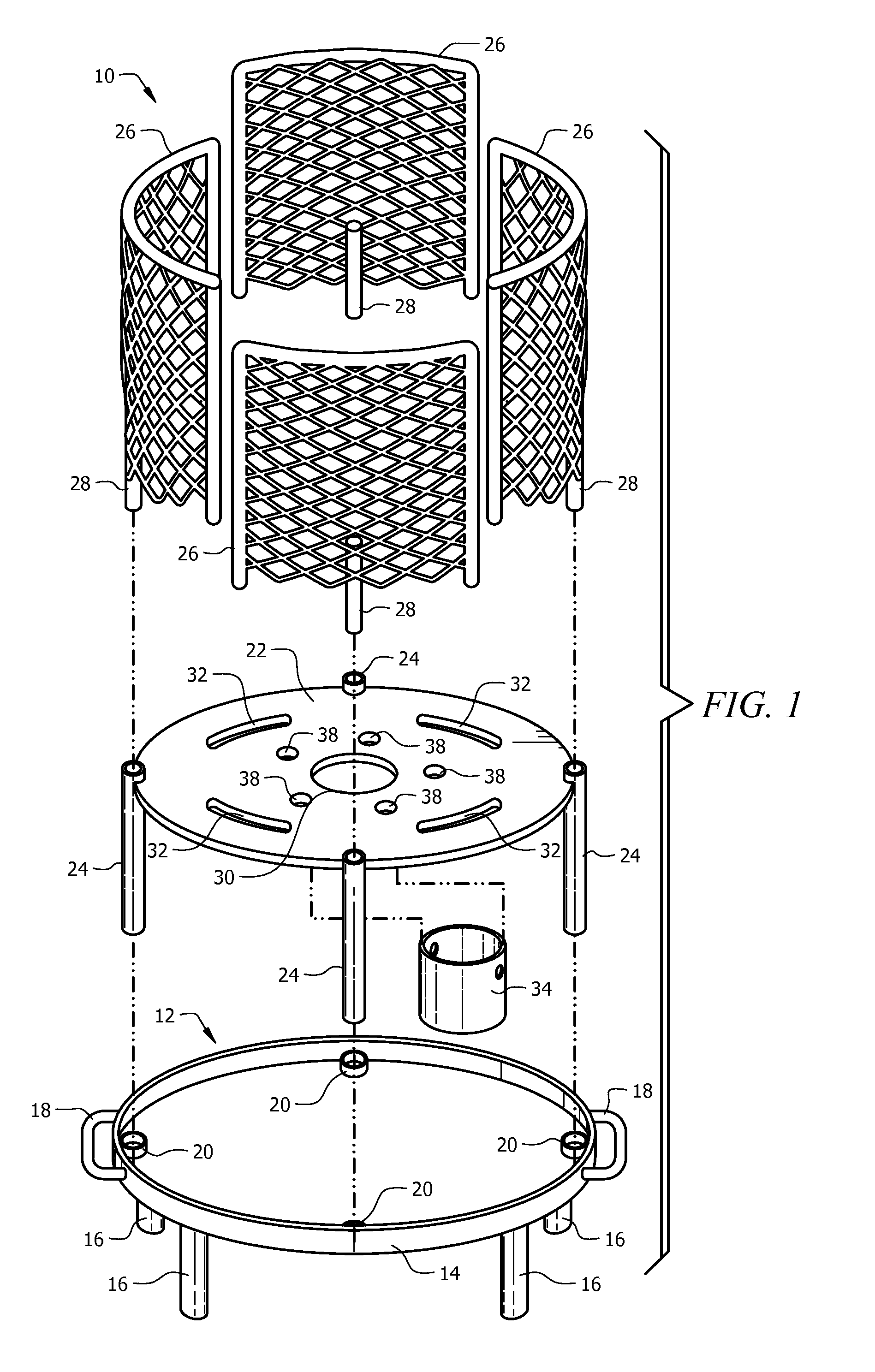
[0038]Circular log-supporting plate 22 has a diameter that, in this first embodiment, is substantially the same as the diameter of circular bottom plate 12 and is positioned in substantial axial alignment with circular bottom plate 12 in vertically spaced, parallel relation thereto. The amount of vertical spacing is determined by the length of legs, collectively denoted 24, that are secured about the periphery of log-supporting plate 22.

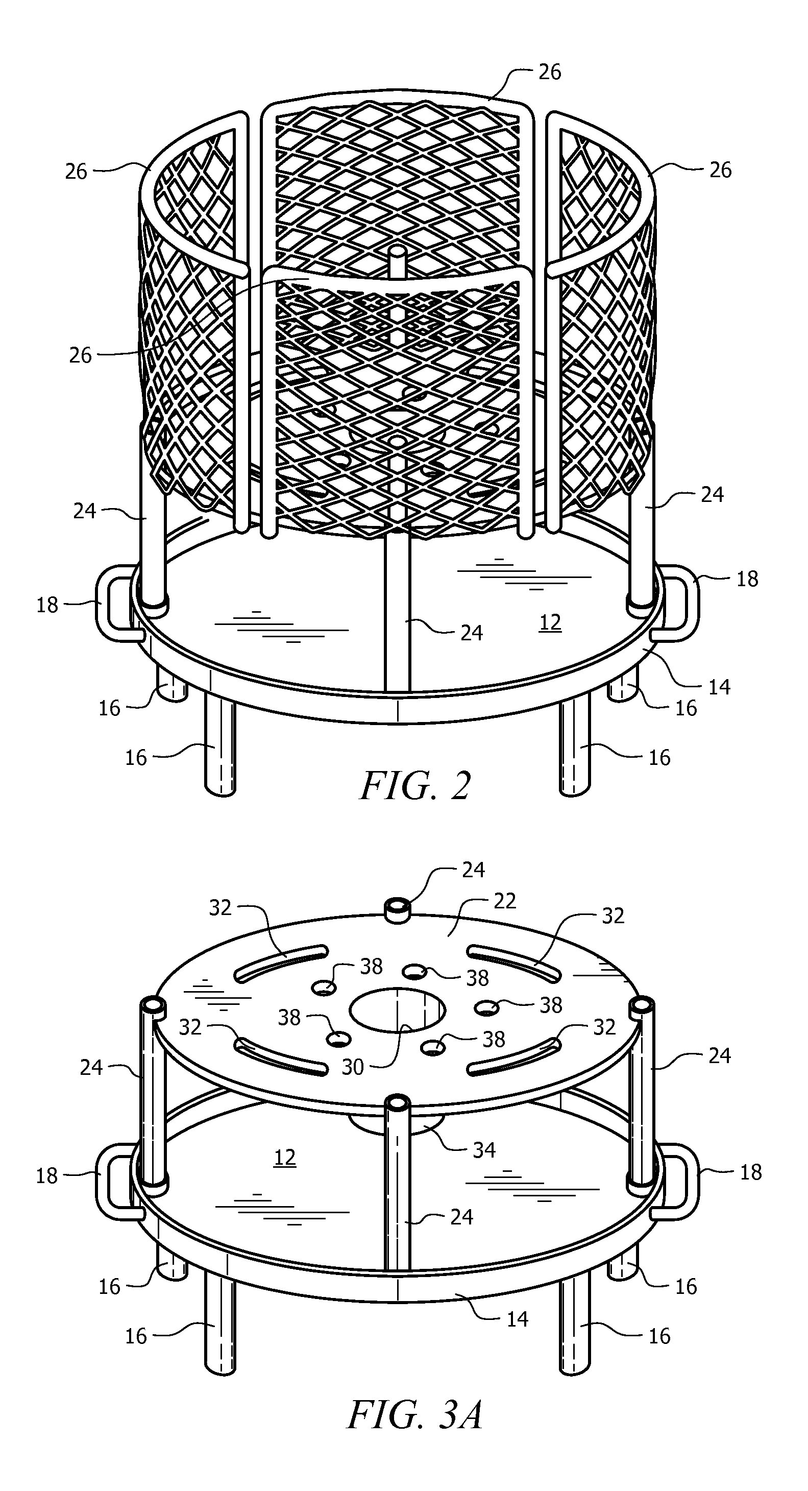
[0039]The lowermost end of each leg 24 is slideably received within a boss 20 when fire pit 10 is in its assembled configuration. The uppermost end of each leg 24 is hollow and extends slightly above the plane of circular log-supporting plate 22 as best depicted in FIGS. 1, 3A and 3B.

[0040]A plurality of arcuate grates, collectively denoted 26, is mounted about the periphery of circular log-supporting plate 22. Each grate 26 is generally rectangular but is arcuate when viewed in plan. More particularly, each grate has a predetermined curvature so tha...

second embodiment

[0048]FIG. 7 depicts a second embodiment where the diameter of circular bottom plate 12 exceeds the diameter of circular log-supporting plate 22. This increases the ash-collecting capacity of circular bottom plate 12. Where the diameter of circular log-supporting plate is fifteen and a half inches (15.5″), the diameter of circular bottom plate may be about eighteen inches (18″) as depicted in FIG. 7, or it may be about twenty four inches (24″). The dimensions are not critical to the invention.

[0049]To disassemble novel fire pit 10, each arcuate grate 26 is lifted to disengage its post 28 from the hollow end of its associated leg 24. Circular log-supporting plate 22 is then lifted to disengage legs 24 from bosses 20. Circular log-supporting plate 22 is then inverted as depicted in FIGS. 4 and 5 so that legs 24 extend upwardly and the inverted circular log-supporting plate 22 is then placed atop circular bottom plate 12. A first grate 26 is then placed atop circular bottom plate 12, a...


PUM


Abstract

A fire pit includes a circular bottom plate and a circular, centrally-apertured log-supporting plate. A plurality of legs secured about the periphery of the log-supporting plate maintain the bottom and log-supporting plates in vertically spaced, parallel relation to one another. Each leg has a hollow uppermost end. A plurality of arcuate grates is mounted about the periphery of the log-supporting plate and a vertically-oriented post is secured to each of the grates, mid-length thereof. Each of the posts has a lowermost end slideably received within the hollow uppermost end of its associated leg to releasably connect each grate to the log-supporting plate. Arcuate openings positioned radially outwardly of the central opening enhance the flow of oxygen into the areas where combustion occurs. The log-supporting plate is inverted and the grates are stacked atop it when the fire pit is in its storage configuration.

Description

BACKGROUND OF THE INVENTION[0001]1. Field of the Invention[0002]This invention relates, generally, to fire pits. A fire pit provides a safe way to burn logs or other combustible materials.[0003]2. Description of the Prior Art[0004]A campfire built on the ground has several disadvantages. For example, the ground may be wet, making fire-starting difficult. Stacking the logs can also be a haphazard activity that does not result in well-ordered logs. Accordingly, oxygen may not flow into the fire in an optimal manner. Moreover, a campfire may also be desired at a campground that lacks camp fire areas.[0005]A fire pit is formed of a suitable metal or a metal alloy and has the advantage of spacing the logs or other combustible materials away from the ground. Fire pits can also be used in campgrounds that lack dedicated campfire areas.[0006]The known fire pits lack means for arranging logs in a non-haphazard manner. Perhaps more importantly, conventional fire pits are also of large, bulky ...

Claims


Application Information

Patent Timeline
IPC IPC(8): A47J37/07F24C1/16F24B1/181
CPCF24B1/181F24B3/00
Inventor MAU, PAUL A.
Owner MAU PAUL A
Why Eureka
Try Eureka