De-icing and/or anti-icing system for the leading edge of an aircraft wing

a leading edge and aircraft technology, applied in the direction of electrical equipment, power plant arrangements/mountings, heating element shapes, etc., can solve the problems of reducing the performance of the aircraft's engine, and affecting the performance of the aircraft. achieve the effect of keeping the temperature substantially constan

Inactive Publication Date: 2015-03-31
SAFRAN NACELLES
View PDF35 Cites 6 Cited by
  • Summary
  • Abstract
  • Description
  • Claims
  • Application Information

AI Technical Summary

Benefits of technology

[0012]The use of infrared emitting members is particularly advantageous: such emitters, commercially available, make it possible to eliminate any withdrawal of hot air on the engines; they have an excellent radiated power / weight ratio: typically in the vicinity of 500 W for 100 g; they take up little space and can easily be changed; they have a long lifetime, typically greater than 10,000 h; they have a strong emissivity, typically in the vicinity of 97% at 800° C. over a spectrum between 1.5 μm and 10 μm (in comparison, a quartz tube has an emissivity in the vicinity of 70%); they have a low thermal inertia, typically allowing, for a 1000 W emitter, a temperature rise of 700° C. in 100 seconds; they make it possible to eliminate the lightning sensitivity problems, since they can be mounted inside the cavity defined by the leading edge or by the air intake lip; they are particularly adapted to anti-icing, since they make it possible to achieve a high surface energy, greater than 70 kW per square meter; they consume little electric current, due to their excellent efficiency, greater than 95%: such an efficiency is due to the fact that the infrared emitting member used is close to a full radiator and the infrared radiation heats the materials, which absorb it, but not the air situated between the emitting member and these materials.
[0027]The invention also concerns a method for controlling a system according to the preceding, in which one interrupts the operation of said power supply means for short periods during which one must make other equipment of said aircraft function, such as a thrust reverser with electric actuators: given the thermal inertia of the heated parts, this method makes it possible to have maximal power for said other equipment of the aircraft, while keeping the temperature substantially constant in the areas to be de-iced.

Problems solved by technology

The formation of ice on the leading edges of an aircraft wing or on the air intake lips of aircraft engines poses many problems, including added weight, imbalance between the port and starboard portions, and, in the specific case of engine air intakes, the formation of blocks of ice capable of penetrating the engine and causing considerable damage.
Anti-icing is necessary in particular in the case of engines comprising portions made from composite materials, such as fan blades: in such cases, it is necessary to eliminate any risk of ice reaching the engine, the composite materials not being able to resist such a shock.
Although these pneumatic systems are relatively effective, they have a number of drawbacks: they are bulky, heavy, and degrade the performance of the aircraft's engines.
Although these electric systems are relatively effective, they have a number of drawbacks: their production is delicate, they are sensitive.

Method used


Image

  • De-icing and/or anti-icing system for the leading edge of an aircraft wing
  • De-icing and/or anti-icing system for the leading edge of an aircraft wing
  • De-icing and/or anti-icing system for the leading edge of an aircraft wing

Examples


Embodiment Construction

[0038]In the following, the system according to the invention will be described when it is integrated with an air intake lip of an aircraft engine.

[0039]It must, however, be remembered that the invention can also apply to a leading edge of an aircraft wing.

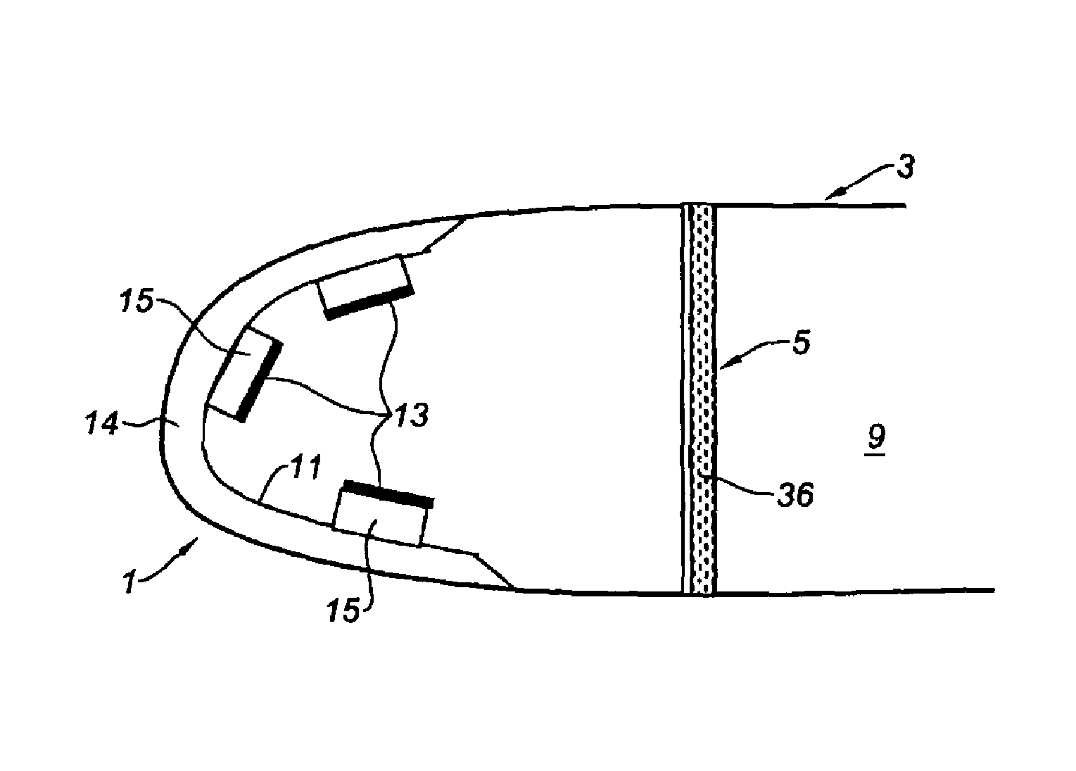
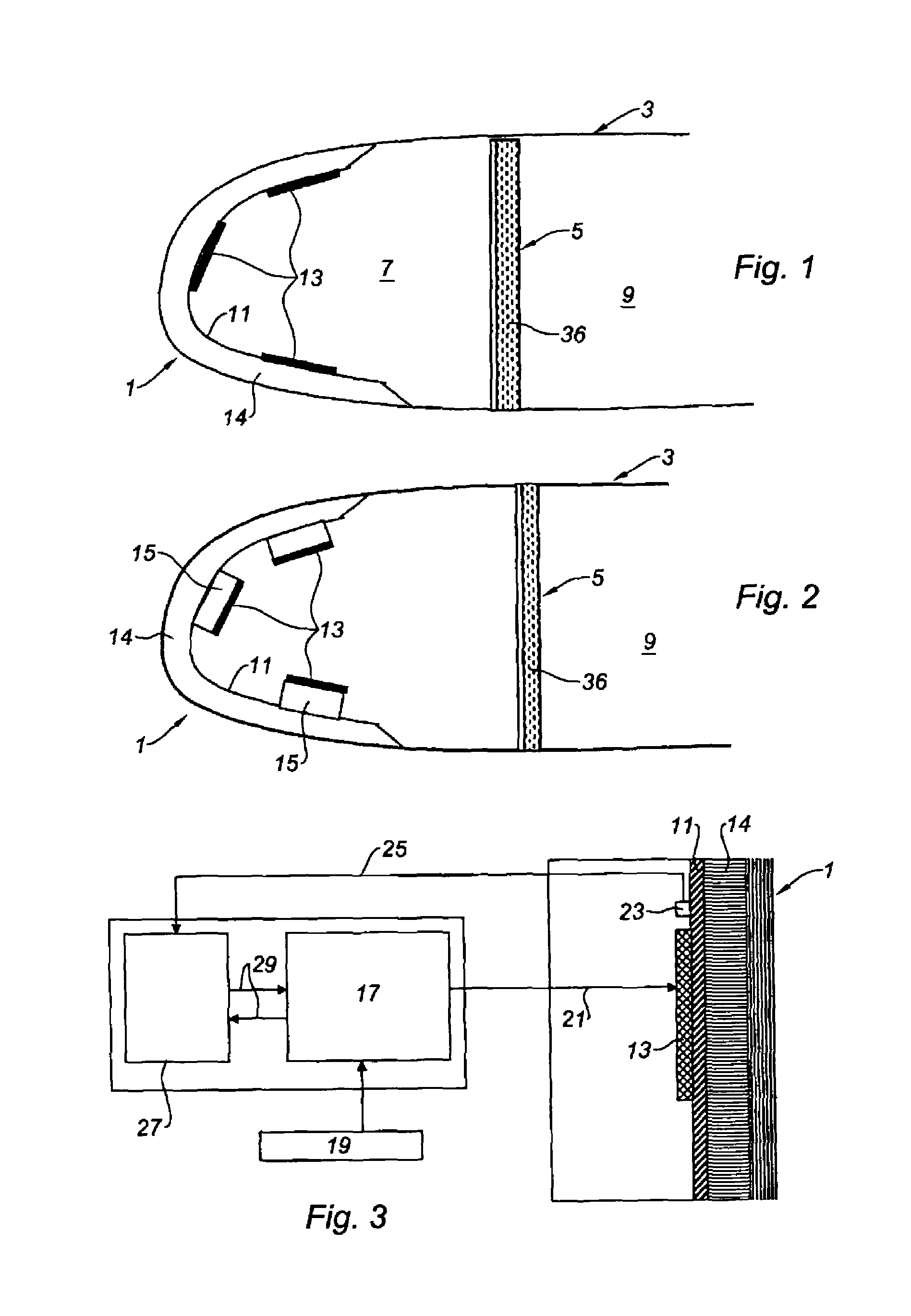
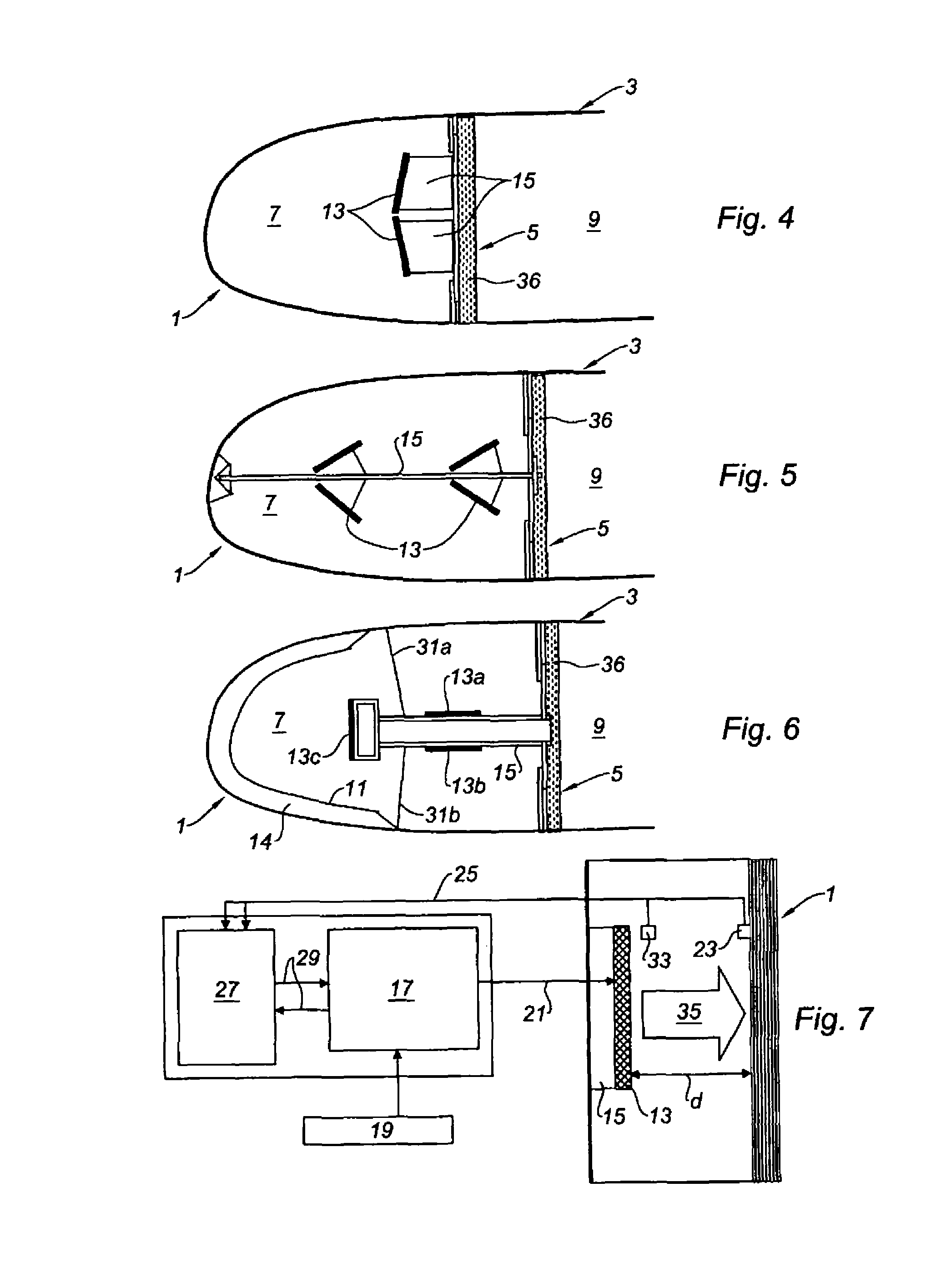
[0040]We will now refer to FIG. 1, which shows an air intake 3 lip 1 of the aircraft engine.

[0041]As known in itself, the air intake of an aircraft engine, which is part of the nacelle surrounding said engine, is a sort of substantially annular shroud making it possible to capture outside air and orient it toward the fan, then toward the compressor of the aircraft engine.

[0042]The lip 1 of this air intake 3 is the leading edge thereof in a way, i.e. the edge that separates the stream of air entering the engine from that flowing toward the outside of the nacelle.

[0043]As known in itself, the air intake 3 generally comprises a partition 5 called “front partition” separating the cavity 7 defined by the lip 1 from the rest of the inne...


PUM


Abstract

The invention relates to a de-icing and / or anti-icing system for the leading edge of an aircraft wing or for the lip (1) of the air intake of an aircraft engine, characterised in that it includes a plurality of infrared emitting members (13) arranged inside said leading edge or said lip (1), power supply means (17) for said emitters (13), and means (27) for controlling said power supply means (17).

Description

TECHNICAL FIELD[0001]The present invention relates to a de-icing and / or anti-icing system for the leading edge of an aircraft wing or for an air intake lip of an aircraft engine, and a method for controlling such a system.BACKGROUND[0002]The formation of ice on the leading edges of an aircraft wing or on the air intake lips of aircraft engines poses many problems, including added weight, imbalance between the port and starboard portions, and, in the specific case of engine air intakes, the formation of blocks of ice capable of penetrating the engine and causing considerable damage.[0003]To this end, a number of de-icing or anti-icing systems have been developed in the aeronautics field, recalling here that de-icing consists of evacuating ice that has already formed, and anti-icing consists of preventing the formation of ice.[0004]Anti-icing is necessary in particular in the case of engines comprising portions made from composite materials, such as fan blades: in such cases, it is ne...

Claims


Application Information

Patent Timeline
Patent Type & Authority Patents(United States)
IPC IPC(8): B64D15/12B64D33/02
CPCB64D15/12B64D2033/0233
Inventor GUILLERMOND, ALAINLE DOCTE, THIERRY
Owner SAFRAN NACELLES
Why Eureka
Try Eureka