Method and arrangement in pneumatic material conveying system

a conveying system and pneumatic technology, applied in the field of pneumatic conveying systems, can solve the problems of noise, dust and fine particles in the outlet pipe, high energy consumption, etc., and achieve the effect of reducing the energy consumption of the system, and reducing the amount of outlet air

Inactive Publication Date: 2015-03-31
MARICAP OY
View PDF41 Cites 8 Cited by
  • Summary
  • Abstract
  • Description
  • Claims
  • Application Information

AI Technical Summary

Benefits of technology

[0007]The arrangement according to the invention has several remarkable advantages. By means of the arrangement according to the invention, pump elements of the system itself can be used for draining the material conveying system and for conveying material to a transport container. By utilizing the suction / pressure of the material conveying system, waste is conveyed for example to the tank of a transport vehicle. Now the transport vehicle can be any possible vehicle provided with a suitable container, such as a shipping container or the like. Consequently, a special truck provided with a suction pump, or a corresponding vehicle, is not needed in the arrangement according to the invention for draining the material conveying system. This results in remarkable savings both financially and with respect to energy consumption. When the system piping is arranged to comprise a circuit where at least part of the conveyor air circulates, the amount of outlet air can be reduced. At the same time, energy consumption in the system is reduced. By maintaining both underpressure and blowing, there can be achieved an efficient circulation of conveyor air in the circuit, and an efficient transport of material in the conveyor pipe. The amount of outlet air can be essentially reduced by an arrangement according to the invention, and at the same time possible problems with dust and fine particles in the outlet pipe can be eliminated. The arrangement according to the invention also essentially alleviates the problem with noise known in the prior art. As the amount of inlet air is reduced, energy consumption is likewise reduced. By opening and closing the system feed points according to the invention, there is achieved an efficient material transport to the conveyor pipe and forwarding in the conveyor pipe, and simultaneously the noise effect caused by the operation of the system can be maintained low. When the conveyor pipe of the material conveying system is arranged to be composed of several functional sections, i.e. sub-circuits, both the conveying of material in the conveyor piping and the draining of the feed points to the conveyor pipe can be efficiently arranged. Blockages can be efficiently cleared by making the conveyor air circulate in the opposite direction. In a loop piping, the direction of circulation of the conveyor air can be easily changed. The arrangement according to the invention is applicable both in conventional conveying systems including one or several conveyor pipes, and in conveying systems with a loop piping.

Problems solved by technology

The vacuum conveying systems typically have, among others, the following problems: high energy consumption, high air flow in the piping, problems with noise, dust and fine particles in the outlet pipe.

Method used


Image

  • Method and arrangement in pneumatic material conveying system
  • Method and arrangement in pneumatic material conveying system
  • Method and arrangement in pneumatic material conveying system

Examples


Embodiment Construction

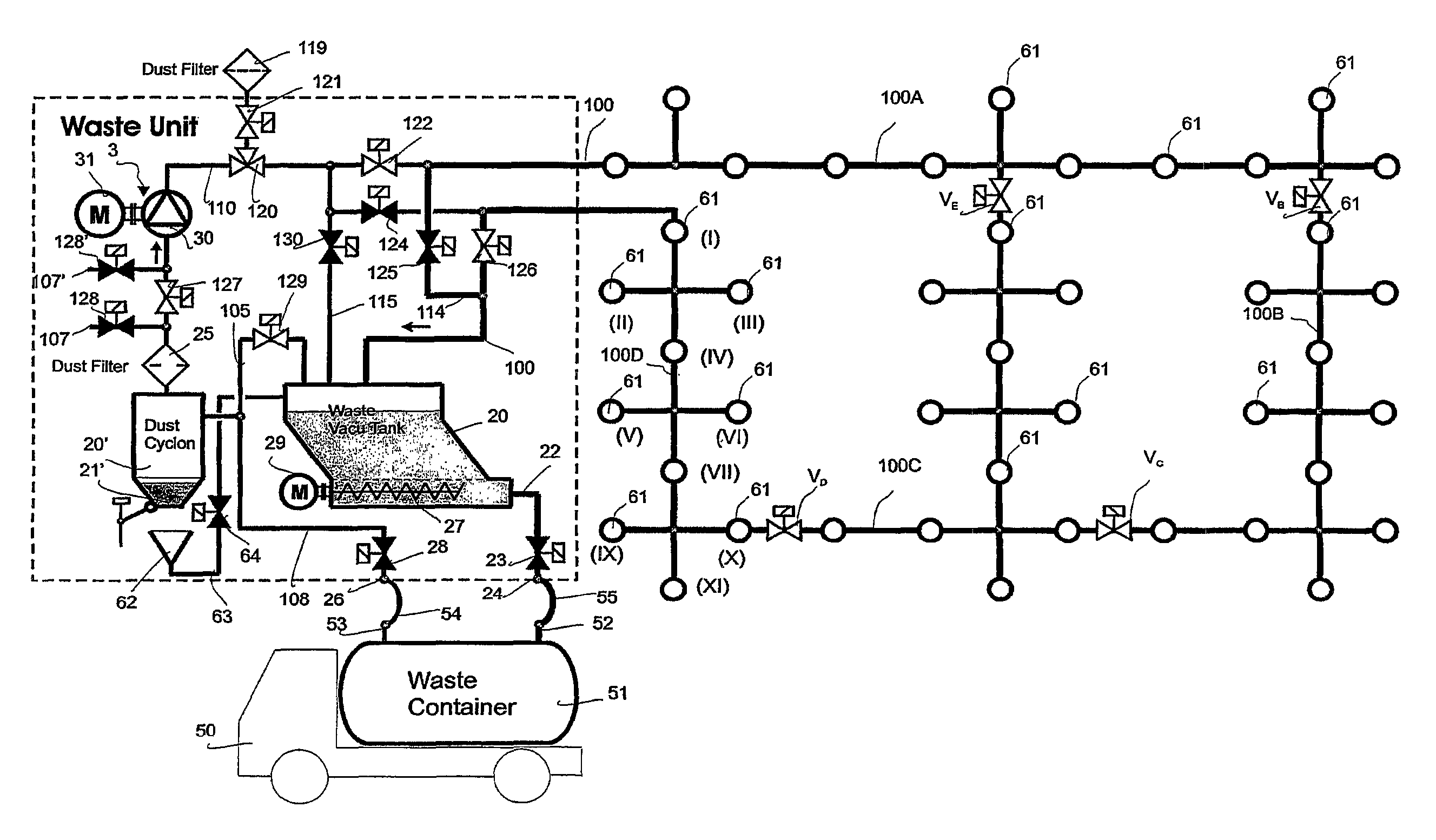
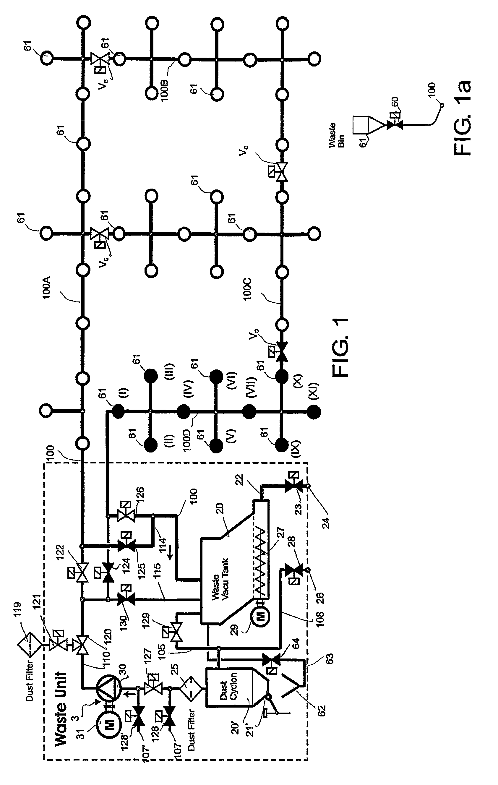
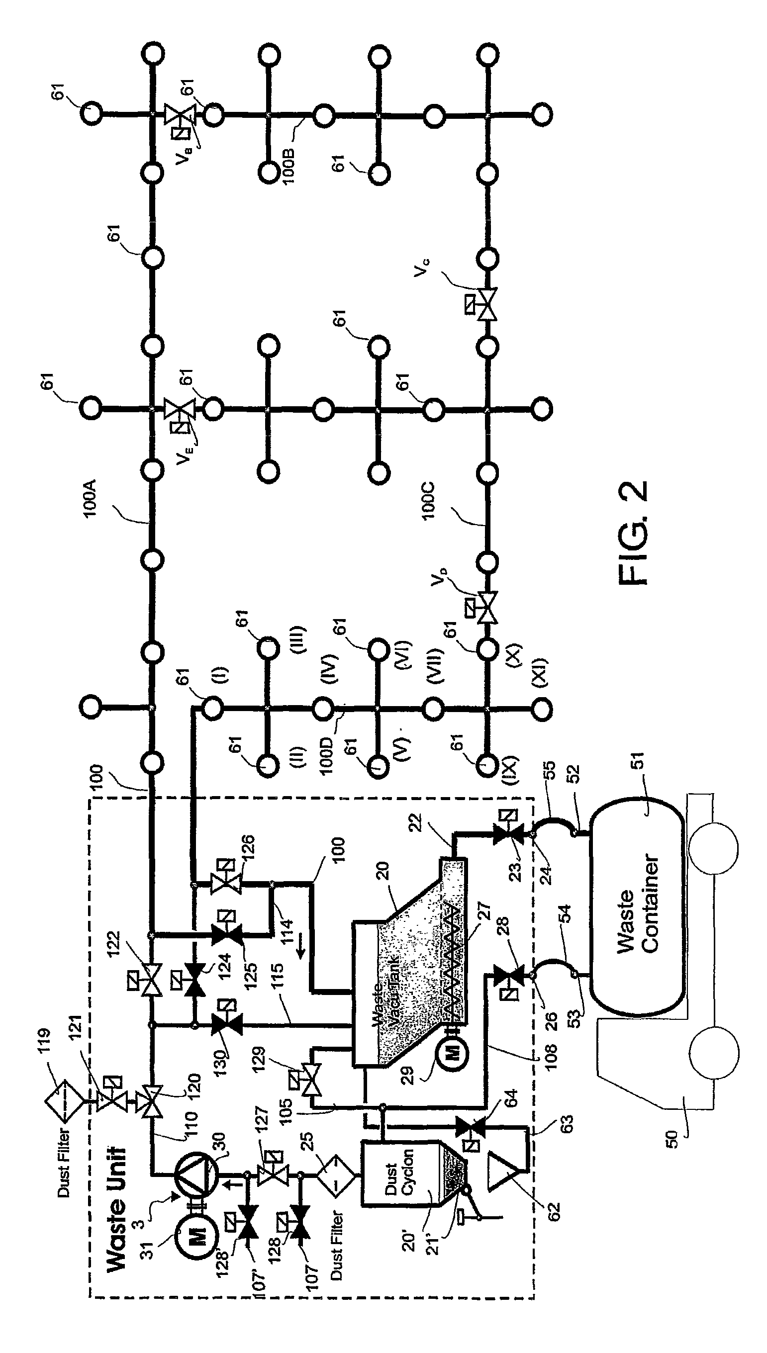
[0015]FIG. 1 is a simplified schematical illustration of a pneumatic material conveying system according to the invention, particularly a waste conveying system. The drawing shows a material conveyor pipe 100, along which pipe there is arranged at least one, but typically several feed points 61. A feed point 61 is the feed station of the material to be conveyed, particularly waste material, through which feed point the material to be conveyed, particularly waste material, such as household waste, is fed to the conveying system. The system may comprise several feed stations 61, through which the material to be conveyed is fed to the conveyor piping 100, 100A, 100B, 100C, 100D, 100E. In the drawing, the feed station 61 is designated by a spot, and by opening and closing a locking element, such as a valve element 60, provided in connection with the feed station, material can be conveyed from the feed point to the conveyor pipe. FIG. 1a illustrates in more detail a feed point 61 and its...


PUM


Abstract

A method in a pneumatic material conveying system, such as in a waste conveying system, said conveying system comprising at least one feed point (61) of material, particularly waste material; a material conveyor pipe (100) that is connectable to the feed point (61); and a separator device (20), where the material to be conveyed is separated from the conveyor air; as well as means (3) for creating a pressure difference in the conveyor pipe (100), at least for the duration of the process of conveying the material. In the method, material is conveyed further from the separator device (20) to the transport container (51), particularly a waste container, by employing in the conveying of material from the separator device to the transport container means (3) of the material conveying system for creating a pressure difference.

Description

BACKGROUND OF INVENTION[0001]The invention relates generally to pneumatic conveying systems, such as vacuum conveying systems, particularly to collecting and conveying waste, for instance household waste.[0002]There are known systems where waste is conveyed in a piping by means of suction. In these, waste is conveyed by suction for long distances in the piping. Apparatuses are utilized, for instance, for conveying waste in different institutions. Typical for them is that a vacuum apparatus is used for achieving a pressure difference, in which apparatus underpressure in the conveyor pipe is provided with vacuum generators, such as vacuum pumps or ejector equipment. In the conveyor pipe, there is typically arranged at least one valve element, and by opening and closing said valve element, make-up air coming in the conveyor pipe is regulated. The vacuum conveying systems typically have, among others, the following problems: high energy consumption, high air flow in the piping, problems...

Claims


Application Information

Patent Timeline
Patent Type & Authority Patents(United States)
IPC IPC(8): B65G53/00B65F5/00B65G53/24
CPCB65G53/24B65F5/005B65F5/00
Inventor SUNDHOLM, GORAN
Owner MARICAP OY
Why Eureka
Try Eureka