Method for arc welding

a technology of arc welding and arc welding, which is applied in the direction of welding/cutting media/materials, welding apparatus, manufacturing tools, etc., can solve the problems of molten metal of the wire to grow too much, a longer time and a larger welding current to open the short circuit, and a time-consuming and labor-intensive process, so as to reduce the short-circuit current and reduce the effect of sputtering

Active Publication Date: 2015-03-31
PANASONIC INTELLECTUAL PROPERTY MANAGEMENT CO LTD
View PDF16 Cites 2 Cited by
  • Summary
  • Abstract
  • Description
  • Claims
  • Application Information

AI Technical Summary

Benefits of technology

[0008]An object of the present invention is to provide a method and apparatus for arc welding which can reduce sputtering in the welding start period. The reduction of sputtering is achieved by making the increase slopes of a short-circuit current and the current value at the inflection point, which is the change point of the different increase slopes of the short-circuit current between the welding start period and the steady-state welding period.
[0010]This method can reduce an increase in the short-circuit current even when no weld pool has yet been formed in the base material immediately after welding is started. As a result, the molten metal of the wire can properly grow, thereby reducing sputtering when the short circuit opens.
[0012]This structure can reduce an increase in the short-circuit current even when no weld pool has yet been formed in the base material immediately after welding is started. As a result, the molten metal of the wire can properly grow, thereby reducing sputtering when the short circuit opens.
[0014]This structure can reduce an increase in the short-circuit current even when no weld pool has yet been formed in the base material immediately after welding is started. As a result, the molten metal of the wire can properly grow, thereby reducing sputtering when the short circuit opens.
[0015]As described above, the present invention, the increase slopes of a short-circuit current and the current value at the inflection point, which is the change point of the increase slopes of the short-circuit current are made different between the welding start period and the steady-state welding period. This method can reduce an increase in the short-circuit current even when no weld pool has yet been formed in the base material immediately after welding is started. As a result, the molten metal of the wire can properly grow, thereby reducing sputtering when the short circuit opens.

Problems solved by technology

A welding operation includes a sputter removal process, which is considered a time inefficient process.
Thus, in the welding start period, it takes a longer time and a larger welding current to open the short circuit.
This may cause the molten metal of the wire to grow too much, thereby generating small sputters when the short-circuit opens.

Method used


Image

  • Method for arc welding
  • Method for arc welding
  • Method for arc welding

Examples


first exemplary embodiment

[0026]The present first exemplary embodiment describes a method for arc welding first, and then describes an arc welding apparatus using this method.

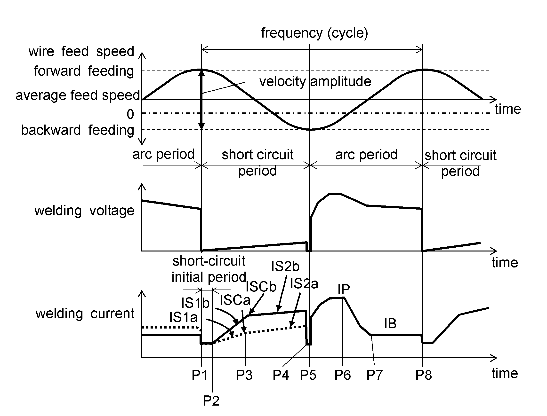
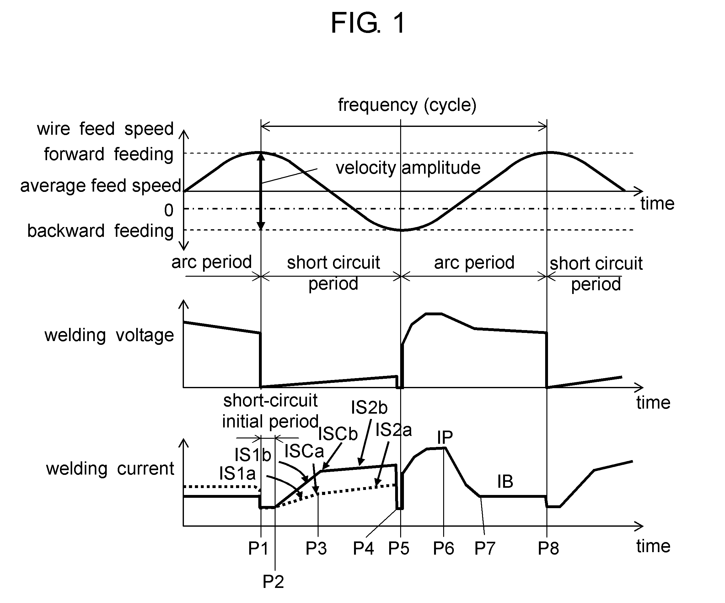
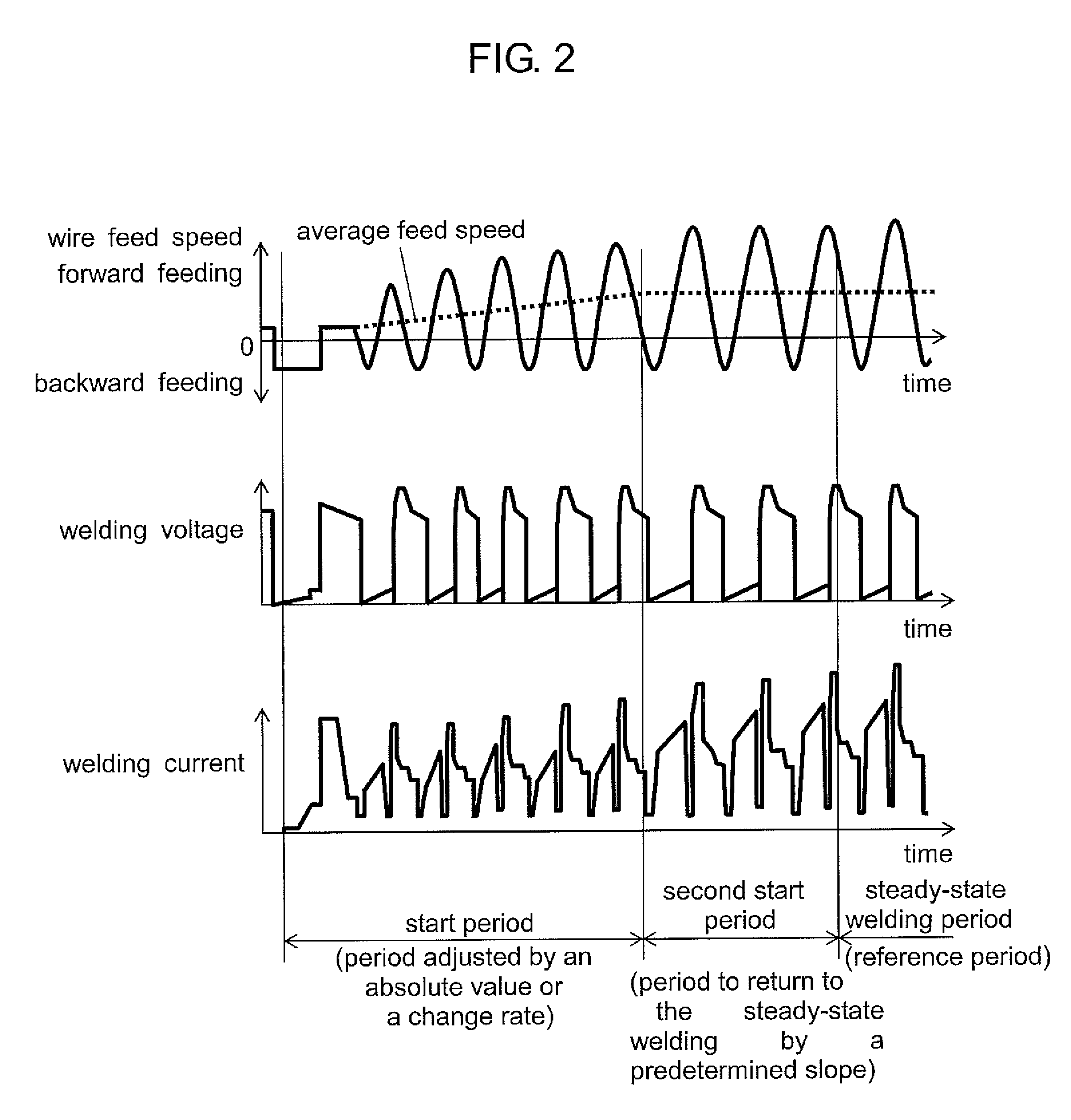
[0027]FIGS. 1 and 2 show time waveforms of a wire feed speed, a welding current, and a welding voltage in consumable electrode arc welding according to the first exemplary embodiment in which a short-circuit state and an arc state are alternated. FIG. 2 shows time waveforms of a wire feed speed, a welding current, and a welding voltage in each of a welding start period, a second start period, and a steady-state welding period. The time waveforms of the wire feed speed, the welding current, and the welding voltage shown in FIG. 1 are about the steady-state welding period.

[0028]As shown in FIG. 1, a time point P1 is when a short circuit occurs. At the time point P1, a short-circuit initial period is started. A time point P2 is when the short-circuit initial period is ended. At the time point P2, it is started to output a first increase sl...


PUM

PropertyMeasurementUnit
speedaaaaaaaaaa
currentaaaaaaaaaa
currentaaaaaaaaaa

Abstract

A method for arc welding can control the increase slopes of the short-circuit current and the inflection point of the increase slopes in the welding start period to be smaller than in the steady-state welding period. Thus, the increase slopes of the short-circuit current and the inflection point are made different between the welding start period and the steady-state welding period, thereby reducing sputtering in the welding start period.

Description

TECHNICAL FIELD[0001]The present invention relates to a method and apparatus for arc welding in which welding is performed by alternating a short-circuit state and an arc state.BACKGROUND ART[0002]A welding operation includes a sputter removal process, which is considered a time inefficient process. To reduce the numbers of times of the sputter removal process, it is necessary to reduce sputtering. A well-known technique to reduce sputtering is a consumable electrode arc welding in which welding is performed by feeding a welding wire in alternating forward and backward directions and by alternating a short-circuit state and an arc state (see, for example, Patent Literature 1). The following is a description, with reference to FIG. 9, of an example of a method for controlling arc welding in which welding is performed by alternating a short-circuit state and an arc state while feeding a welding wire as a consumable electrode.[0003]FIG. 9 shows time waveforms of a wire feed speed, a we...

Claims


Application Information

Patent Timeline
Patent Type & Authority Patents(United States)
IPC IPC(8): B23K9/00B23K9/09B23K9/10
CPCB23K9/09B23K9/1012
Inventor FUJIWARA, JUNJIKAWAMOTO, ATSUHIRONAKAGAWA, AKIRA
Owner PANASONIC INTELLECTUAL PROPERTY MANAGEMENT CO LTD
Why Eureka
Try Eureka