Anti-viscin thread control method

A control method and anti-sticking technology, applied in manufacturing tools, arc welding equipment, welding equipment, etc., can solve problems such as failure of arc ignition, achieve good arc starting, good weld appearance, and reduce sputtering. Effect

Inactive Publication Date: 2015-06-10
DAIHEN CORP
View PDF7 Cites 7 Cited by
  • Summary
  • Abstract
  • Description
  • Claims
  • Application Information

AI Technical Summary

Problems solved by technology

If welding is started with slag adhering to the tip of the wire, even if the wire is in contact with the base metal, the arc will fail to strike due to the slag being interposed.

Method used


Image

  • Anti-viscin thread control method
  • Anti-viscin thread control method
  • Anti-viscin thread control method

Examples


Embodiment approach 1

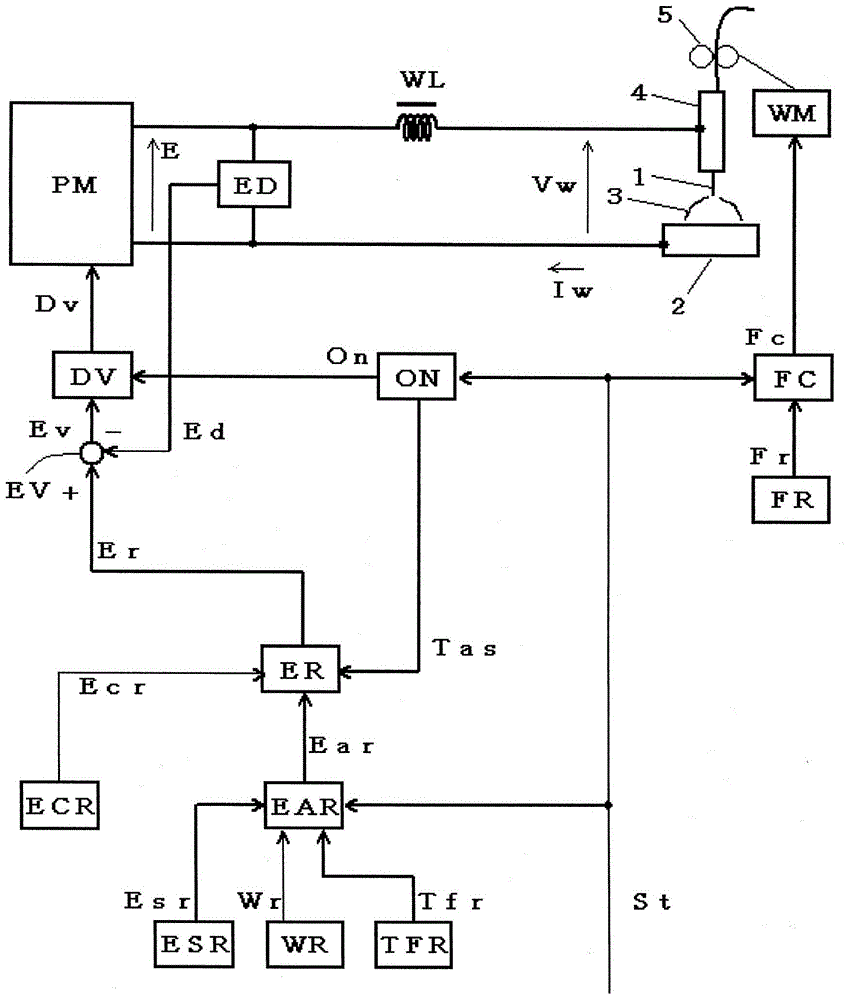
[0037] figure 1 It is a block diagram of a welding power source for implementing the anti-sticking control method according to Embodiment 1 of the present invention. Hereinafter, each block will be described with reference to this figure.

[0038]The power supply main circuit PM receives a commercial power supply (not shown) such as 3-phase 200V as an input, and outputs an output voltage E through inverter control based on a drive signal Dv described later. Although not shown in the figure, this power supply main circuit PM includes a primary rectification circuit for rectifying commercial power, a capacitor for smoothing rectified direct current, an inverter circuit for converting smoothed direct current into high-frequency alternating current, and A high-frequency transformer for stepping down the high-frequency AC to a voltage suitable for arc welding and a secondary rectification circuit for rectifying the stepped-down high-frequency AC. The reactor WL smoothes the abov...

Embodiment approach 2

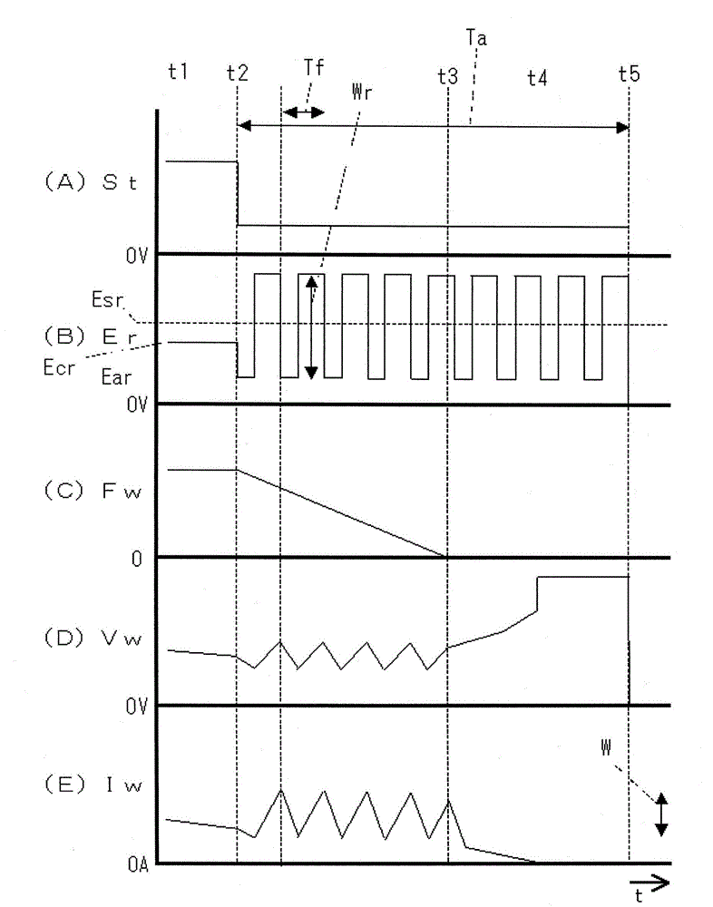
[0058] In the invention of Embodiment 1, the anti-sticking control period Ta is set to a predetermined value. On the other hand, in the invention of Embodiment 2, the anti-sticking control period Ta is set to a period including a predetermined number of oscillation waveforms of the welding voltage Vw and the welding current Iw.

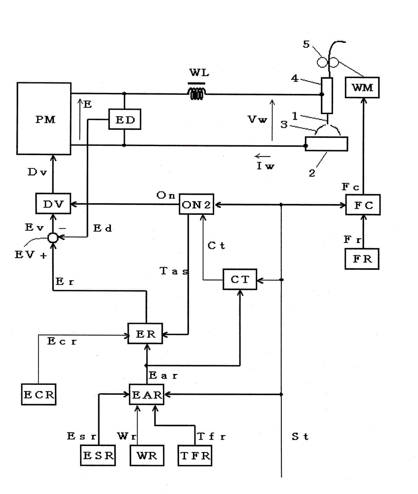
[0059] image 3 It is a block diagram of a welding power source for implementing the anti-sticking control method according to Embodiment 2 of the present invention. This figure corresponds to the above figure 1 , to assign the same symbol to the same module, and the description will not be repeated. The graph is in figure 1 On the basis of adding a cycle counting circuit CT, the figure 1 The starting circuit ON of the original is replaced by the second starting circuit ON2. Hereinafter, these blocks will be described with reference to the figure.

[0060] The cycle counting circuit CT takes the welding start signal St and the anti-sticking v...

Embodiment approach 3

[0070] In the invention according to Embodiment 3, a predetermined period has elapsed from the time point when the voltage setting signal Er was switched to the anti-sticking voltage setting value Ear (the time point when the time point shifted to the anti-sticking control period Ta) (preceding The amplitude (amplitude setting signal Wr) and / or cycle (period setting signal Tfr) of the anti-sticking voltage setting Ear value after the period Ts) is set to be larger than the value before the predetermined period elapses.

[0071] Figure 5 It is a block diagram of a welding power source for implementing the anti-sticking control method according to Embodiment 3 of the present invention. This figure corresponds to the above figure 1 , assign the same symbol to the same module, and will not repeat it. The graph is in figure 1 The second amplitude setting circuit WR2, the second cycle setting circuit TFR2 and the leading period setting circuit TSR are added on the basis of f...


PUM


Abstract

The invention provides an anti-viscin thread control method comprising the following the steps: feeding a solder wire doped with solder agent; carrying out constant voltage control according to a voltage setting signal (Er), thus outputting a welding voltage (Vw) and a welding current (Iw), and carrying out welding; if a welding start signal (St) is changed into a stop instruction, than the voltage setting signal (Er) is switched into an anti-viscin thread voltage setting value (Ear), thus stop welding. The anti-viscin thread voltage setting value (Ear) is set in vibration waveform, so the welding current (Iw) is set to vibration waveforms of triangle shape or sine wave shape, and the anti-viscin thread voltage setting value (Ear) is set to prevent short circuit in an anti-viscin thread control period (Ta); welding agent in the solder wire can be gasified so as to prevent slags from attaching to the front end of the solder wire. The solder wire with solder agent is used for arc welding so as to prevent slags from attaching to the front end of the solder wire, thus providing better arcing property.

Description

technical field [0001] The present invention relates to an anti-stick wire control method for arc welding using a flux-doped welding wire. Background technique [0002] Arc welding using a fluxed wire using carbon dioxide as a shielding gas, self-shielded arc welding using a self-shielded fluxed wire without using a shielding gas, etc. The droplet transfer method in is the spray transfer method. In the jet transfer method, the tip of the wire is melted by the arc heat and becomes fine particles, which are then transferred to the molten pool. In the spray transfer method, the droplet is not a short-circuit transfer, but a transfer by free fall. [0003] In arc welding using a fluxed wire (hereinafter referred to as "fluxed wire welding"), a welding power source with a constant voltage characteristic is used to feed the wire at a constant speed. Welding with a flux-filled wire is characterized in that the amount of spatter produced is small and the appearance of the weld be...

Claims


Application Information

Patent Timeline
Patent Type & Authority Applications(China)
IPC IPC(8): B23K9/10
CPCB23K9/10
Inventor 森大辅上园敏郎刘忠杰
Owner DAIHEN CORP
Why Eureka
Try Eureka