Anti-sticking control method
A control method and anti-sticking technology, which is applied in the direction of manufacturing tools, welding equipment, arc welding equipment, etc., can solve the problems of arc ignition failure and other problems, and achieve the effect of good arc starting, stable change, and good appearance of weld seam
- Summary
- Abstract
- Description
- Claims
- Application Information
AI Technical Summary
Problems solved by technology
Method used
Image
Examples
Embodiment approach 1
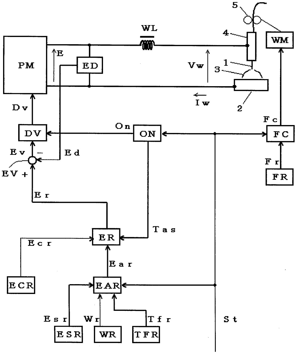
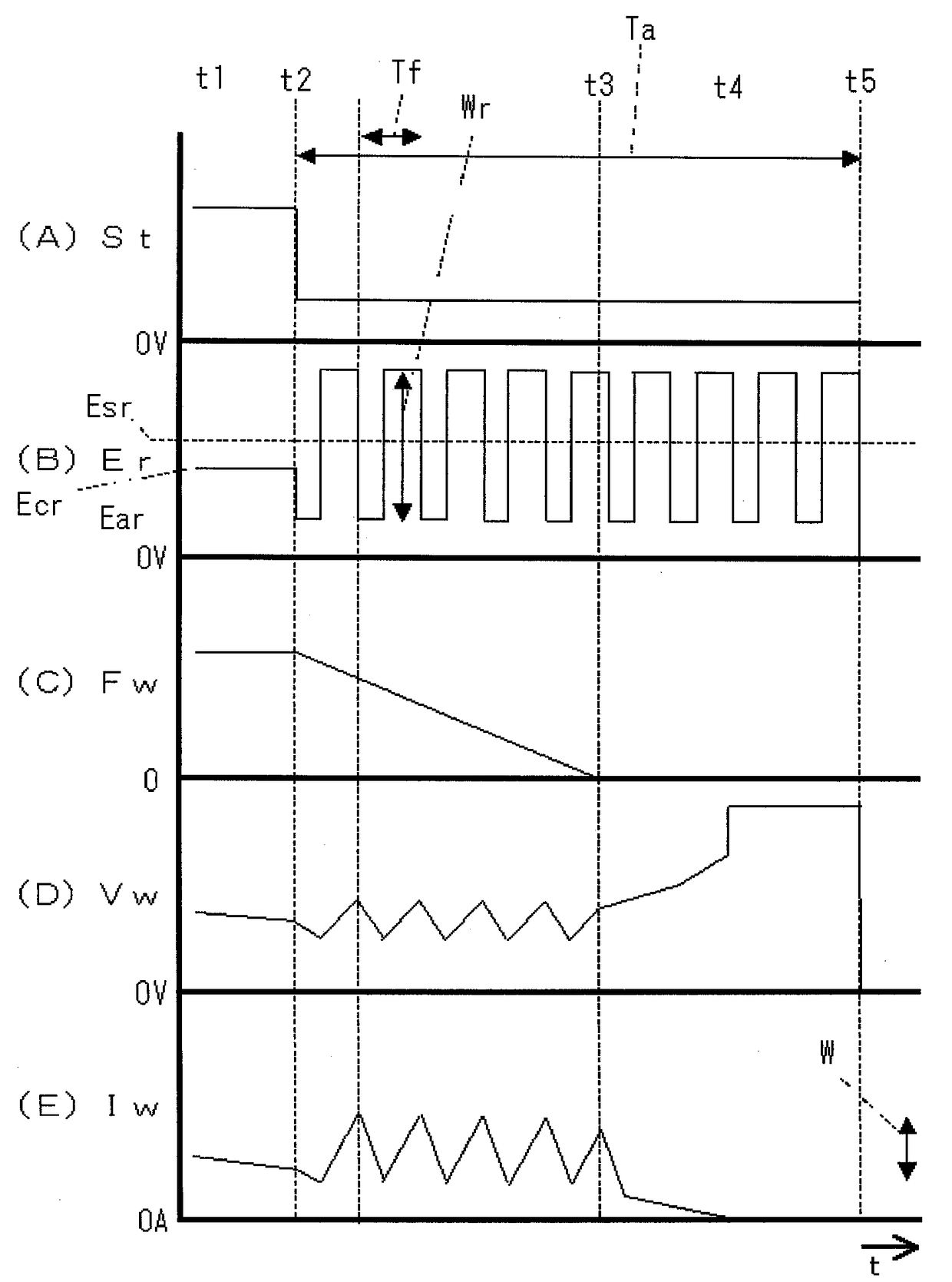
[0037] figure 1 It is a block diagram of a welding power source for implementing the anti-sticking control method according to Embodiment 1 of the present invention. Hereinafter, each block will be described with reference to this figure.
[0038]The power supply main circuit PM receives a commercial power supply (not shown) such as 3-phase 200V as an input, and outputs an output voltage E through inverter control based on a drive signal Dv described later. Although not shown in the figure, this power supply main circuit PM includes a primary rectification circuit for rectifying commercial power, a capacitor for smoothing rectified direct current, an inverter circuit for converting smoothed direct current into high-frequency alternating current, and A high-frequency transformer for stepping down the high-frequency AC to a voltage suitable for arc welding and a secondary rectification circuit for rectifying the stepped-down high-frequency AC. The reactor WL smoothes the abov...
Embodiment approach 2
[0058] In the invention of Embodiment 1, the anti-sticking control period Ta is set to a predetermined value. On the other hand, in the invention of Embodiment 2, the anti-sticking control period Ta is set to a period including a predetermined number of oscillation waveforms of the welding voltage Vw and the welding current Iw.
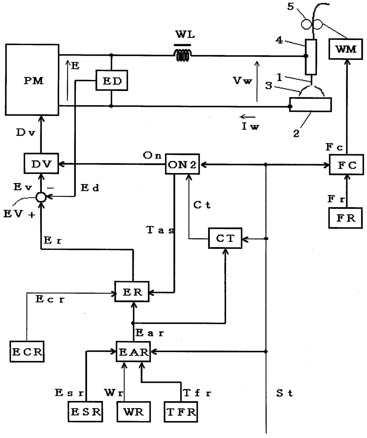
[0059] image 3 It is a block diagram of a welding power source for implementing the anti-sticking control method according to Embodiment 2 of the present invention. This figure corresponds to the above figure 1 , to assign the same symbol to the same module, and the description will not be repeated. The graph is in figure 1 On the basis of adding a cycle counting circuit CT, the figure 1 The starting circuit ON of the original is replaced by the second starting circuit ON2. Hereinafter, these blocks will be described with reference to the figure.
[0060] The cycle counting circuit CT takes the welding start signal St and the anti-sticking v...
Embodiment approach 3
[0070] In the invention according to Embodiment 3, a predetermined period has elapsed from the time point when the voltage setting signal Er was switched to the anti-sticking voltage setting value Ear (the time point when the time point shifted to the anti-sticking control period Ta) (preceding The amplitude (amplitude setting signal Wr) and / or cycle (period setting signal Tfr) of the anti-sticking voltage setting Ear value after the period Ts) is set to be larger than the value before the predetermined period elapses.
[0071] Figure 5 It is a block diagram of a welding power source for implementing the anti-sticking control method according to Embodiment 3 of the present invention. This figure corresponds to the above figure 1 , assign the same symbol to the same module, and will not repeat it. The graph is in figure 1 The second amplitude setting circuit WR2, the second cycle setting circuit TFR2 and the leading period setting circuit TSR are added on the basis of f...
PUM
 Abstract
Description
Claims
Application Information
 - R&D
- Intellectual Property
- Life Sciences
- Materials
- Tech Scout
- Unparalleled Data Quality
- Higher Quality Content
- 60% Fewer Hallucinations
Browse by: Latest US Patents, China's latest patents, Technical Efficacy Thesaurus, Application Domain, Technology Topic, Popular Technical Reports.
© 2025 PatSnap. All rights reserved.Legal|Privacy policy|Modern Slavery Act Transparency Statement|Sitemap|About US| Contact US: help@patsnap.com


