Supercharge Your Innovation With Domain-Expert AI Agents!

Flip-flop circuit having set/reset circuit

a flip-flop circuit and circuit technology, applied in the field of flip-flop circuit design, can solve the problems of failure to have a set/reset function, design a frequency divider that may be employed in high-speed operations, and inability to use a flip-flop

Active Publication Date: 2015-03-31
SILICON MOTION INC (TW)
View PDF3 Cites 5 Cited by
  • Summary
  • Abstract
  • Description
  • Claims
  • Application Information

AI Technical Summary

Benefits of technology

The present invention proposes a flip-flop circuit that can be used in a high-speed frequency divider and has both a set / reset function. This circuit solves the issue of ensuring reliable and efficient functioning of the frequency divider.

Problems solved by technology

However, if advanced manufacture processes are unavailable, it is not feasible for a flip-flop used in the frequency divider to be realized by a standard D-type flip-flop element.
However, the TSPC flip-flop is only allowed to use a single-phase trigger clock in order to avoid clock signals with different phases from concurrently pulling internal data to a high electric potential and a low electric potential, and thus fails to have a set / reset function.
Therefore, how to design a frequency divider that may be employed in high-speed operations as well as a flip-flop circuit having a set / reset function is an important issue.

Method used


Image

  • Flip-flop circuit having set/reset circuit
  • Flip-flop circuit having set/reset circuit
  • Flip-flop circuit having set/reset circuit

Examples


Embodiment Construction

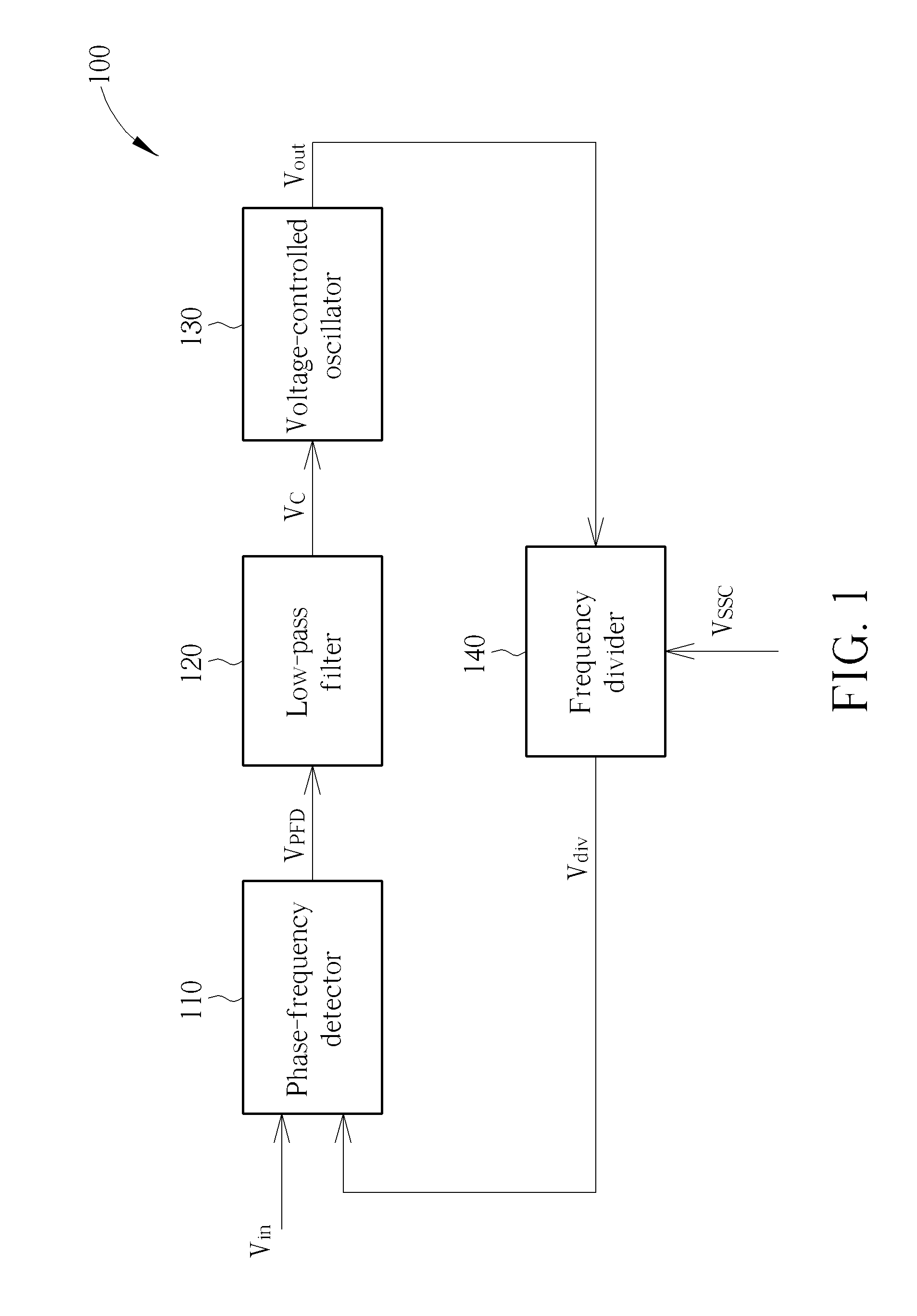
[0015]Please refer to FIG. 1, which is a schematic diagram illustrating a phase-locked loop 100 according to an embodiment of the present invention. As shown in FIG. 1, the phase-locked loop 100 includes a phase-frequency detector 110, a low-pass filter 120, a voltage-controlled oscillator 130 and a frequency divider 140. The phase-locked loop 100 is a high-speed phase-locked loop circuit, and an output clock Vout generated by the phase-locked loop 100 has a frequency higher than 1 GHz. Besides, in this embodiment, the phase-locked loop 100 is a spread spectrum clock phase-locked loop circuit.

[0016]Regarding operations of the phase-locked loop 100, the phase-frequency detector 110 first compares an input signal Vin with a feedback signal (i.e., a frequency-divided signal Vdiv outputted by frequency divider 140) to generate a detecting result VPFD, and then the low-pass filter 120 processes the detecting result VPFD to generate a control signal VC; next, the voltage-controlled oscill...


PUM


Abstract

A flip-flop circuit includes an input stage circuit, a middle stage circuit, an output stage circuit and a set / reset circuit. The input stage circuit is arranged for receiving a first signal from a first node, and selectively outputting a second signal at a second node according to at least one control signal. The middle stage circuit is coupled to the input stage circuit, and arranged for receiving the second signal, and selectively outputting a third signal at a third node according to the at least one control signal. The output stage circuit is coupled to the middle stage circuit, and arranged for receiving the third signal to output an output signal. The set / reset circuit is coupled to the second node and the third node, and arranged to receiving a set signal and a reset signal, and selectively determining a voltage level of the third signal at the third node.

Description

CROSS REFERENCE TO RELATED APPLICATIONS[0001]This application claims the benefit of U.S. provisional application No. 61 / 665,321, filed on Jun. 28, 2012 and incorporated herein by reference.BACKGROUND OF THE INVENTION[0002]1. Field of the Invention[0003]The disclosed embodiments of the present invention relates to a flip-flop circuit design, and more particularly, to a flip-flop circuit with a circuit structure similar to a true single phase clock (TSPC) structure and having a set / reset function.[0004]2. Description of the Prior Art[0005]In a high-speed phase-locked loop (PLL) circuit, the frequency divider would perform frequency division operation on high-frequency (e.g., above 1 GHz) signals. However, if advanced manufacture processes are unavailable, it is not feasible for a flip-flop used in the frequency divider to be realized by a standard D-type flip-flop element.[0006]In order to solve the above-mentioned problem, the frequency divider may be realized by using a TSPC flip-fl...

Claims


Application Information

Patent Timeline
Patent Type & Authority Patents(United States)
IPC IPC(8): H03K3/00H03K3/013H03K3/356
CPCH03K3/013H03K3/356191
Inventor CHANG, HUI-JU
Owner SILICON MOTION INC (TW)
Features
  • R&D
  • Intellectual Property
  • Life Sciences
  • Materials
  • Tech Scout
  • Unparalleled Data Quality
  • Higher Quality Content
  • 60% Fewer Hallucinations
Learn More