Remote data concentrator

a data concentrator and remote data technology, applied in the field of remote data concentrators, can solve the problems of reducing complexity and saving considerable cost and weight, and achieve the effect of reducing the complexity of rdc software and simple coding of rdc softwar

Active Publication Date: 2015-03-31
AIRBUS OPERATIONS LTD +1
View PDF7 Cites 1 Cited by
  • Summary
  • Abstract
  • Description
  • Claims
  • Application Information

AI Technical Summary

Benefits of technology

[0008]The invention is advantageous in that the RDC is no longer a “dumb” data concentrator simply converting one signal into another, as in the prior art, but instead is interactive in controlling the output device. For example, the RDC can operate autonomously to drive the output device in the event of loss of (primary) command from the remote processor. This avoids the need for a redundant, secondary control system connecting the output device to the remote processor, which reduces complexity and saves considerable cost and weight. Furthermore, the RDC can assess the validity of the remote command and drive the output device according to the best available command resource, giving improved reliability, failure detection and redundancy.
[0017]The configuration table may be adapted to store one or more predetermined states for the output device, and the RDC may be adapted to generate the local command by interrogating the configuration table to select one of the predetermined states according to the input signal. The configuration table enables simple coding of the RDC software. The number of predetermined states may be far fewer than would ordinarily be provided under control of the remote processor and may, for example, be only sufficient to ensure safe operation of the output device. This reduces the complexity of the RDC software.

Problems solved by technology

This avoids the need for a redundant, secondary control system connecting the output device to the remote processor, which reduces complexity and saves considerable cost and weight.

Method used


Image

  • Remote data concentrator
  • Remote data concentrator
  • Remote data concentrator

Examples


first embodiment

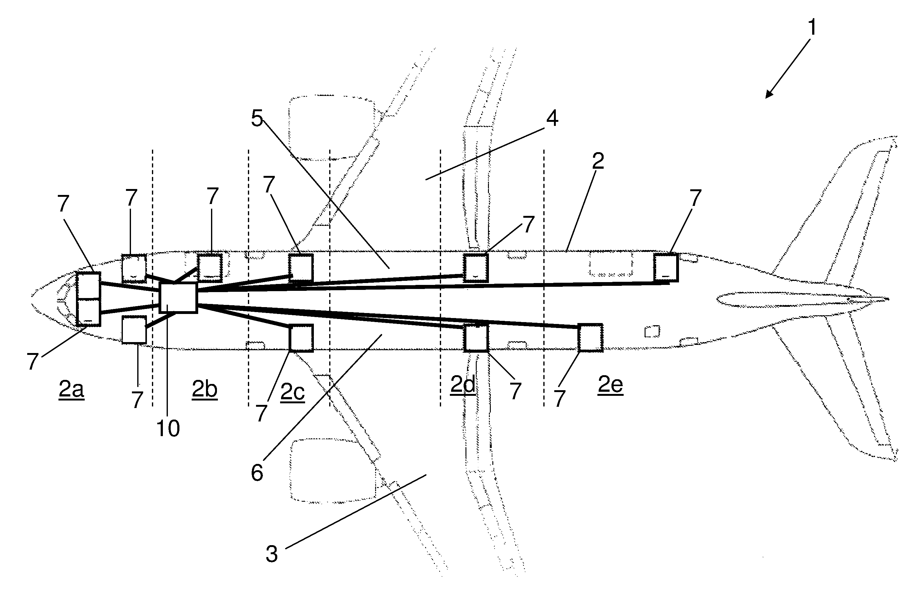
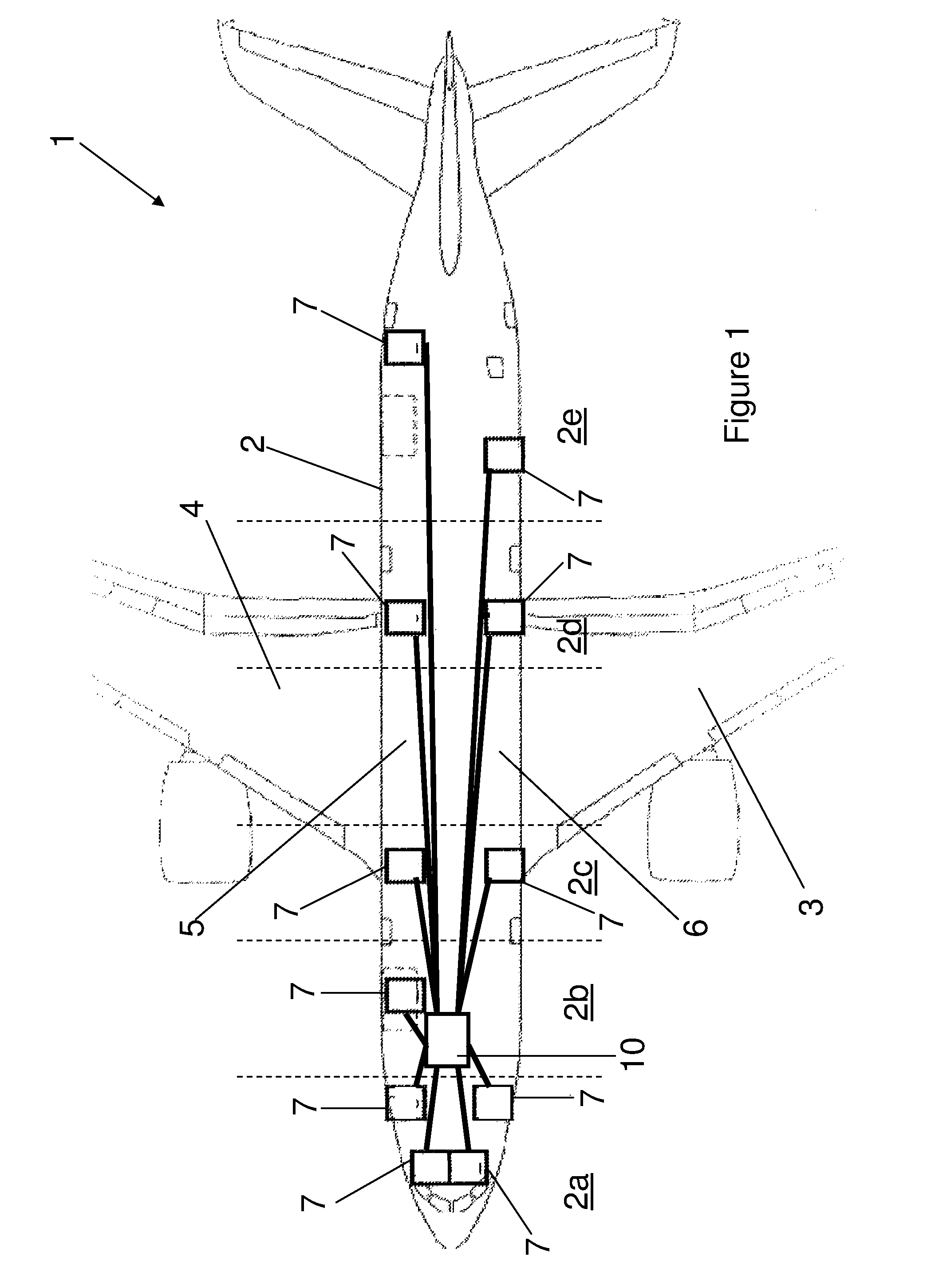
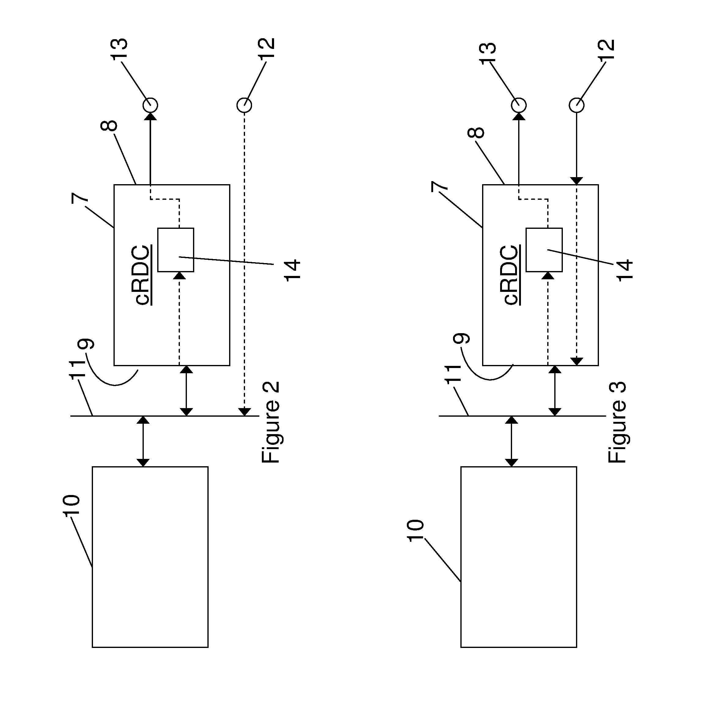
[0030]FIG. 2 illustrates the avionics network including a cRDC 7 having an input / output interface (I / O) 8 for connection to a plurality of input / output devices, which may be Line Replaceable Units (LRUs), and a network interface 9 for connection to a remote processor 10. The network interface 9 of the cRDC 7 is connected to the remote processor 10 over avionics network 11. The network 11 includes one or more data buses, e.g. CAN, ARINC 429 or FlexRay, that form part of the wiring routes 5, 6. The processor 10 is located in the forward fuselage 2b as shown in FIG. 1.

[0031]In FIG. 2, the avionics network includes an input device 12 and an output device 13. For example, the output device 13 may be a valve and the input device 12 may be a sensor for controlling the valve position. The output device is connected to the network 11 via the cRDC 7, and in particular is connected to the I / O 8 of the cRDC 7. The input device 12 is connected to the network 11 by an alternative means. For examp...

fourth embodiment

[0051]As an example of how the fourth embodiment may be employed, the input device 12 may be an aircraft cabin temperature sensor, and the output device 13 may be an aircraft cabin air conditioning unit temperature controller. The software 14b of the cRDC 7b may have stored in the look up table 15 a plurality of discrete settings for the temperature controller. For example, the look up table 15 may store three settings—“Low”, “Medium” and “High”. If the input signal from the temperature sensor 12 indicates a cabin temperature above a predetermined threshold, then the cRDC 7b drives the temperature controller to the low setting. If the cabin temperature sensor 12 indicates a cabin temperature below a predetermined minimum threshold temperature then the cRDC 7b can drive the temperature controller 13 to the “High” setting. If the cabin temperature sensor 12 indicates a cabin temperature between maximum and minimum threshold temperatures then the cRDC 7b may drive the temperature contr...


PUM


Abstract

A remote data concentrator (RDC) for an avionics network, the RDC comprising an input / output interface (I / O) for connection to one or more input / output devices, and a network interface for connection to a remote processor, wherein the RDC is operable to provide communication between the input / output device(s) and the remote processor, and wherein the RDC further comprises a set of instructions for autonomously driving an output device connected to the I / O. Also, an avionics network including the RDC; an aircraft including the RDC; and a method of operating the RDC.

Description

RELATED APPLICATIONS[0001]The present application is a National Phase of PCT / EP2011 / 065579, filed Sep. 8, 2011 and is based on, and claims priority from, Great Britain Application No. 1015756.8, filed Sep. 21, 2010.FIELD OF THE INVENTION[0002]The present invention relates to a remote data concentrator (RDC) for an avionics network. Also, an avionics network including the RDC; an aircraft including the RDC; and a method of operating the RDC.BACKGROUND OF THE INVENTION[0003]Modern aircraft typically include a great number of sensors, effectors (e.g. actuators), etc., connected to an avionics network having one or more central processors. The sensors, effectors, etc. are typically line replaceable units (LRUs) to improve operational effectiveness. The LRUs are typically concentrated at particular locations in the aircraft where systems are installed. To reduce wiring, and therefore weight, a remote data concentrator (RDC) may be used to connect several of the LRUs to the avionics netwo...

Claims


Application Information

Patent Timeline
Patent Type & Authority Patents(United States)
IPC IPC(8): G06F3/00G06F5/00G06F13/38G06F3/06H04L12/40H04L29/08
CPCG06F3/0659H04L67/12H04L67/125H04L2012/4028
Inventor TODD, TIMOTHYNITSCHE, THORSTEN
Owner AIRBUS OPERATIONS LTD
Why Eureka
Try Eureka