Retractable trim vane for amphibious vehicle

a technology for amphibious vehicles and trim vanes, which is applied in the direction of marine propulsion, special-purpose vessels, vessel construction, etc., can solve the problems of creating and affecting drag, and achieve the effects of reducing the end effect drag of separated trim vanes, increasing the dynamic lift of vehicles, and increasing the effective surface area

Inactive Publication Date: 2015-04-07
BAE SYSTEMS LAND & ARMAMENTS LP
View PDF10 Cites 7 Cited by
  • Summary
  • Abstract
  • Description
  • Claims
  • Application Information

AI Technical Summary

Benefits of technology

[0009]The present invention is directed to a trim vane assembly for an amphibious vehicle and comprising a trim vane movable along a generally horizontal path between a deployed position in which the trim vane extends rearward from the vehicle and a stowed position in which the trim vane is positioned beneath the amphibious vehicle. The horizontal path corresponds to the bottom of the vehicle such that trim vane is flush against or received within a horizontal space in the vehicle bottom such that the trim vane supplements the belly armor. Similarly, the trim vane extends from or overlaps with the bottom of the vehicle when extended into the deployed position to provide a continuous bottom face for the vehicle. Conventional stern mounted trim vanes are rotated between a vertical orientation against the rear of the vehicle and a horizontal position extending from the rear of the vehicle. The hinged arrangement typically requires a gap between the trim vane and the rear of the vehicle to allow the trim vane to rotate, which can create and effect drag. In contrast, the sliding arrangement of the present invention allows the trim vane to be extended from the rear of the vehicle without creating a gap between the trim vane and the bottom of the vehicle eliminating the end effect drag of a separated trim vane. The continuous bottom face also increases the effective surface area of the bottom of the vehicle, increases the dynamic lift of the vehicle, which in turn reduces the viscous drag of the water past the vehicle hull allowing the vehicle to travel faster and more efficiently.
[0010]In one aspect, the trim vane assembly can comprise a trim adjustment assembly for rotating the trim vane when the trim vane is positioned in the extended position. The adjustment assembly rotates the trim vane at the rear of the vehicle bottom to position the trim vane at a downward trim angle. The downward trim angle further increases the dynamic lift of the vehicle and further reduces the viscous drag on the vehicle. In this configuration, the trim vane is returned to the stowed position by rotating the trim vane into the horizontal orientation and moving the trim vane along the horizontal path.

Problems solved by technology

The hinged arrangement typically requires a gap between the trim vane and the rear of the vehicle to allow the trim vane to rotate, which can create and effect drag.

Method used


Image

  • Retractable trim vane for amphibious vehicle
  • Retractable trim vane for amphibious vehicle
  • Retractable trim vane for amphibious vehicle

Examples


Embodiment Construction

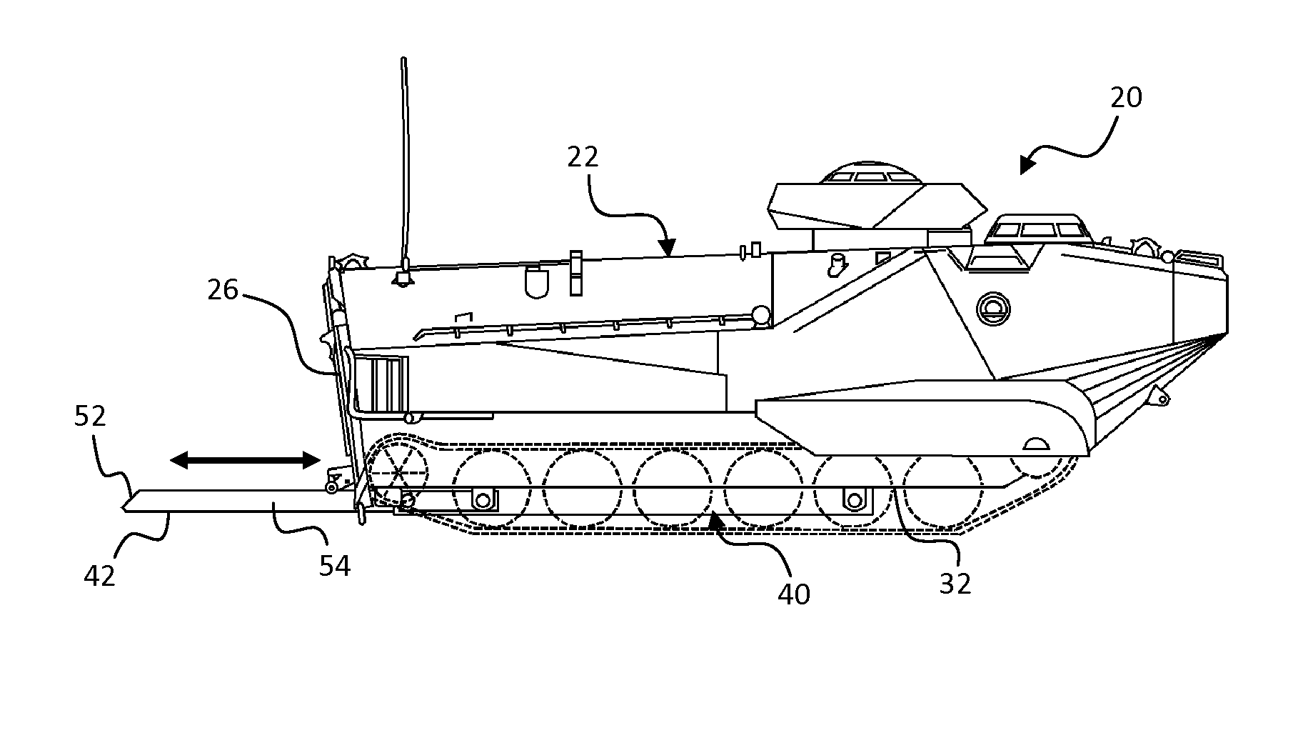
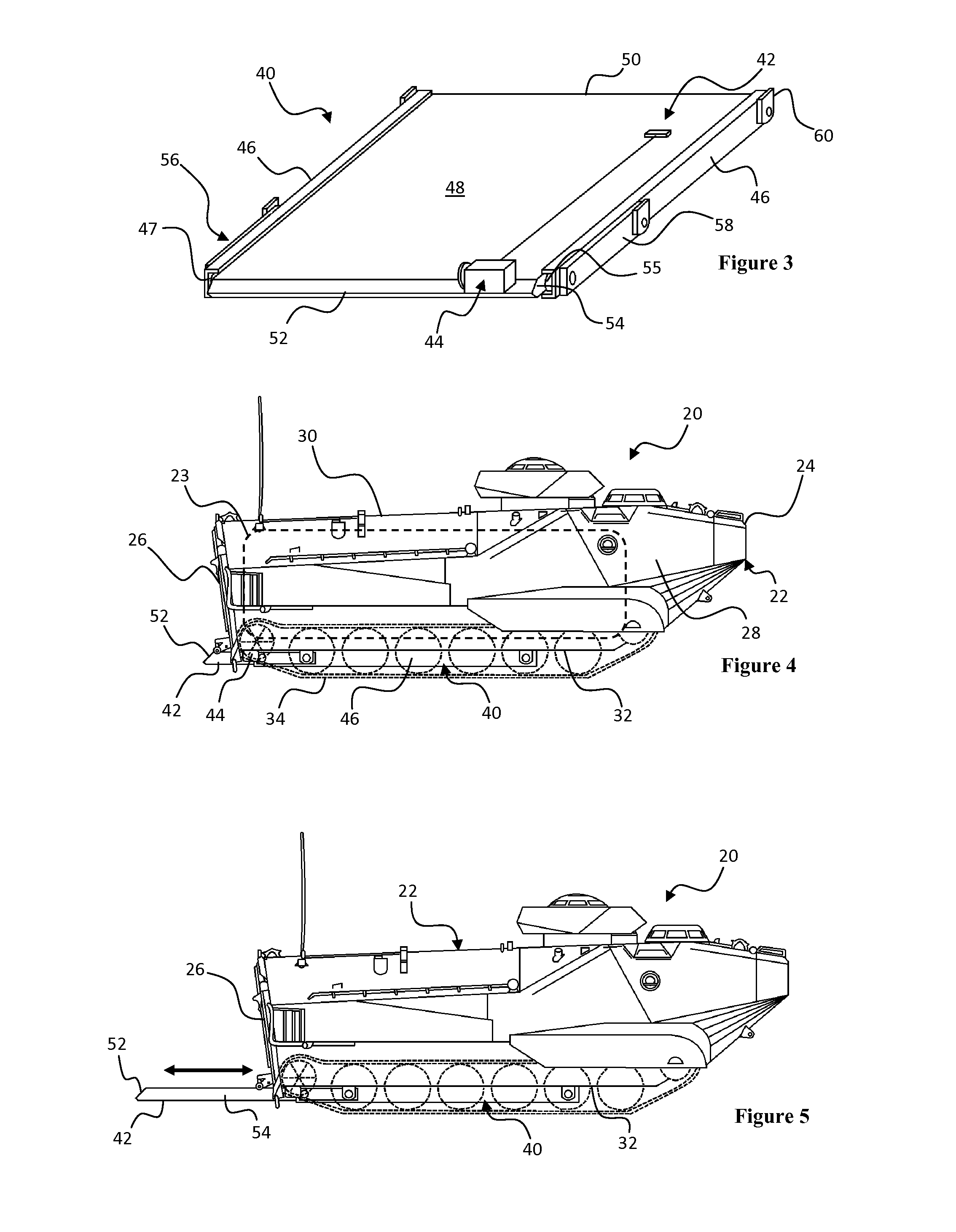
[0026]As depicted in FIGS. 4-8, an amphibious vehicle 20 for use with the present invention can comprise a vehicle body 22 containing a crew compartment 23 and having a front face 24, a rear face 26, two side walls 28, a top side 30 and an underside 32 comprising belly armor. As depicted, the amphibious vehicle 20 is an amphibious variant of the Bradley Fighting Vehicle. However, the present invention can function with an amphibious vehicle 20 having a generally planar underside 32. At least the underside 32 and portions of the front face 24, rear face 26 and side walls 28 are water tight to allow the vehicle body 22 to be at least partially submerged. In one aspect, the vehicle 20 can comprise at least one vehicle hatch 34 in the rear face 26 of the vehicle body 22.

[0027]As depicted in FIGS. 4-8, the vehicle 20 further comprises tank treads 34 extending below the underside 32 of the vehicle body 22 defining a space between the plane defined by the bottom of the treads 34 and the un...


PUM


Abstract

A trim vane assembly for amphibious armored vehicles and having a trim vane movable along a generally horizontal path between a deployed position in which the trim vane extends rearward from the vehicle and a stowed position in which the trim vane is positioned beneath the amphibious vehicle. In the retracted position, the trim vane movable is flush against or received within the vehicle bottom such that the trim vane supplements the belly armor. Similarly, the trim vane extends from or overlaps with the bottom of the vehicle when extended into the deployed position to provide continuous bottom face of the vehicle extending from the front of the vehicle to the end of the trim vane. Conventional trim vanes are rotated between a vertical orientation against the rear of the vehicle and a horizontal position extending from the rear of the vehicle reducing viscous drag.

Description

RELATED APPLICATION[0001]The present application claims the benefit of U.S. Provisional Application No. 61 / 593,066 entitled RETRACTABLE WATER MODE TRIM VANE and filed Jan. 31, 2012, which is incorporated herein in its entirety.FIELD OF THE INVENTION[0002]The present invention is generally directed to a deployable trim vane assembly for improving the hydrodynamic characteristics of amphibious vehicles. Specifically, the present invention is directed to a deployable trim vane movable between a deployed position in which the trim vane extends rearward from the back of the vehicle to improve the hydrodynamics of the vehicle and a retracted position in which the trim vane is positioned beneath the vehicle for improving the ballistic and mine protection of the underside of the vehicle.BACKGROUND OF THE INVENTION[0003]Amphibious vehicles are dual role vehicles having wheels or tracks for moving on land and a water tight hull with a water propulsion means for moving across the water. The in...

Claims


Application Information

Patent Timeline
Patent Type & Authority Patents(United States)
IPC IPC(8): B63B1/32B60F3/00F41H7/02
CPCB63B1/32F41H7/02B60F3/0038
Inventor CHU, PETER C.MCCULLOUGH, MICHAEL KEVINBROWNFIELD, JOHN J.
Owner BAE SYSTEMS LAND & ARMAMENTS LP
Why Eureka
Try Eureka