Dilator assembly, a device for facilitating tracheostomy and methods of making a percutaneous tracheostoma

a tracheostomy and assembly technology, applied in the direction of dilators, tracheal tubes, surgery, etc., can solve the problems of damage to the posterior tracheal wall, serious surgical complications, and the inability to perform both ciaglia techniques by very skilled sta

Inactive Publication Date: 2015-04-07
SAFETRACH
View PDF8 Cites 2 Cited by
  • Summary
  • Abstract
  • Description
  • Claims
  • Application Information

AI Technical Summary

Benefits of technology

[0015]It is second aspect of the present invention to provide a dilator assembly of the kind mentioned in the opening paragraph which can be inserted unobstructed into the trachea in a smooth operation.
[0078]The method for performing percutaneous dilatational tracheostomy is, according to the present invention, particular easy and fast to perform if a stabiliser element is used in step (f) for holding the dilator element and the retractor element together during dilation.

Problems solved by technology

Both Ciaglia techniques are well reputed but can only be performed by very skilled staff.
When performing a percutaneous tracheotomy with all existing techniques, there is a risk of serious surgical complications e.g. damaging the posterior tracheal wall, large neck blood-vessels and fractures of tracheal rings.
Due to a.o. the prerequisite guide wire this known dilator cannot be used when the patient already has an endotracheal tube for ventilation.
Moreover the tracheostomy dilator would take up considerable space if arranged next to an endotracheal tube and be difficult to maneuver without the endotracheal tube gets dislocated.
This known apparatus cannot be inserted if an endotracheal tube already is inserted in the trachea, a.o. due to the presence of the cutting edge that might damage the endotracheal tube, the large diameter of between one to one and a half inch, and the spatial hindrance if an endotracheal tube already is present.

Method used


Image

  • Dilator assembly, a device for facilitating tracheostomy and methods of making a percutaneous tracheostoma
  • Dilator assembly, a device for facilitating tracheostomy and methods of making a percutaneous tracheostoma
  • Dilator assembly, a device for facilitating tracheostomy and methods of making a percutaneous tracheostoma

Examples


Embodiment Construction

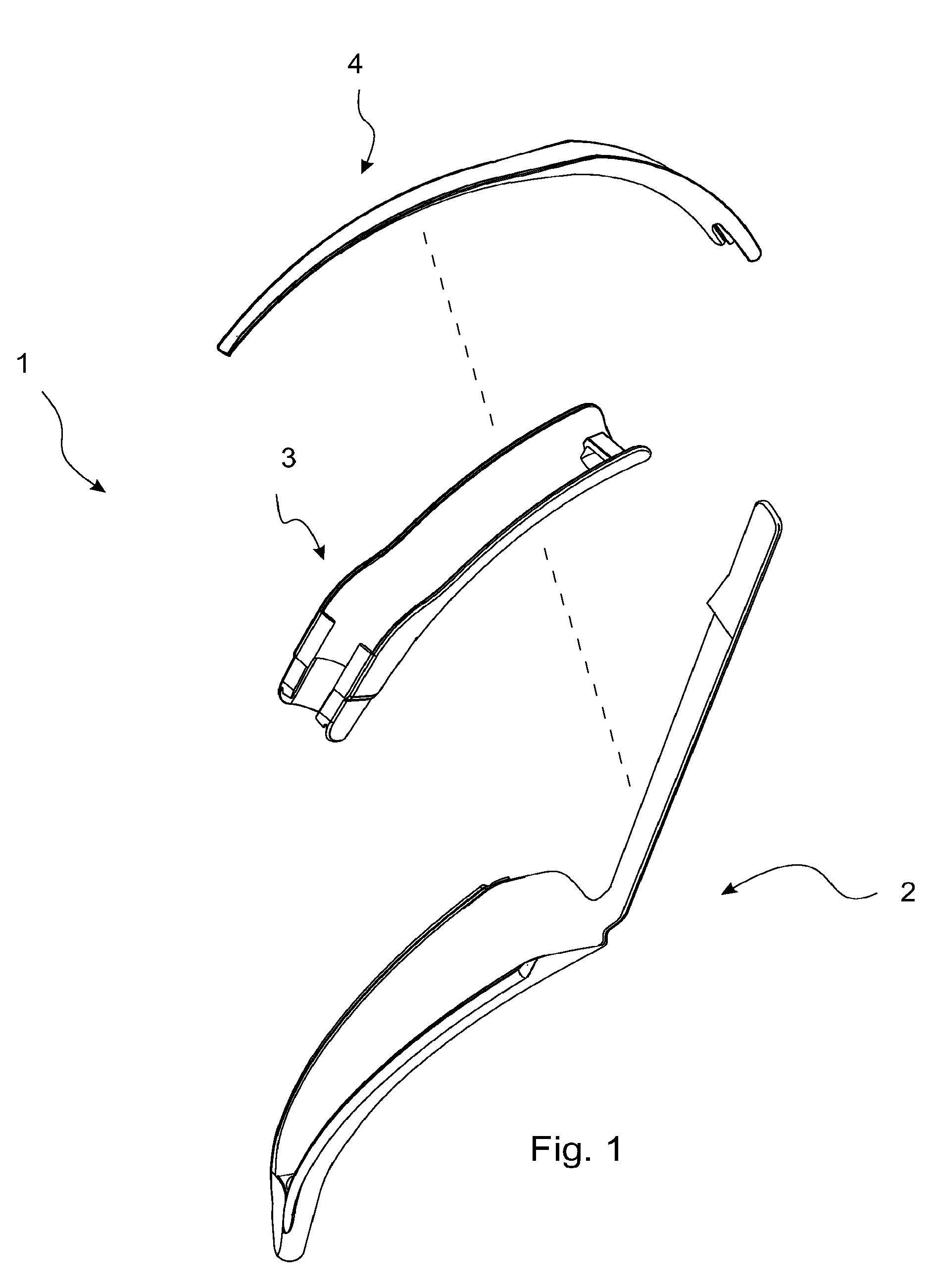
[0101]FIG. 1 shows the components for a preferred embodiment of a dilator assembly 1. The dilator assembly includes a dilator element 2, a retractor element 3 and a stabiliser element 4, the details of which will be explained in more detailed with references to the following FIGS. 1-15 in which the component are illustrated from various angles.

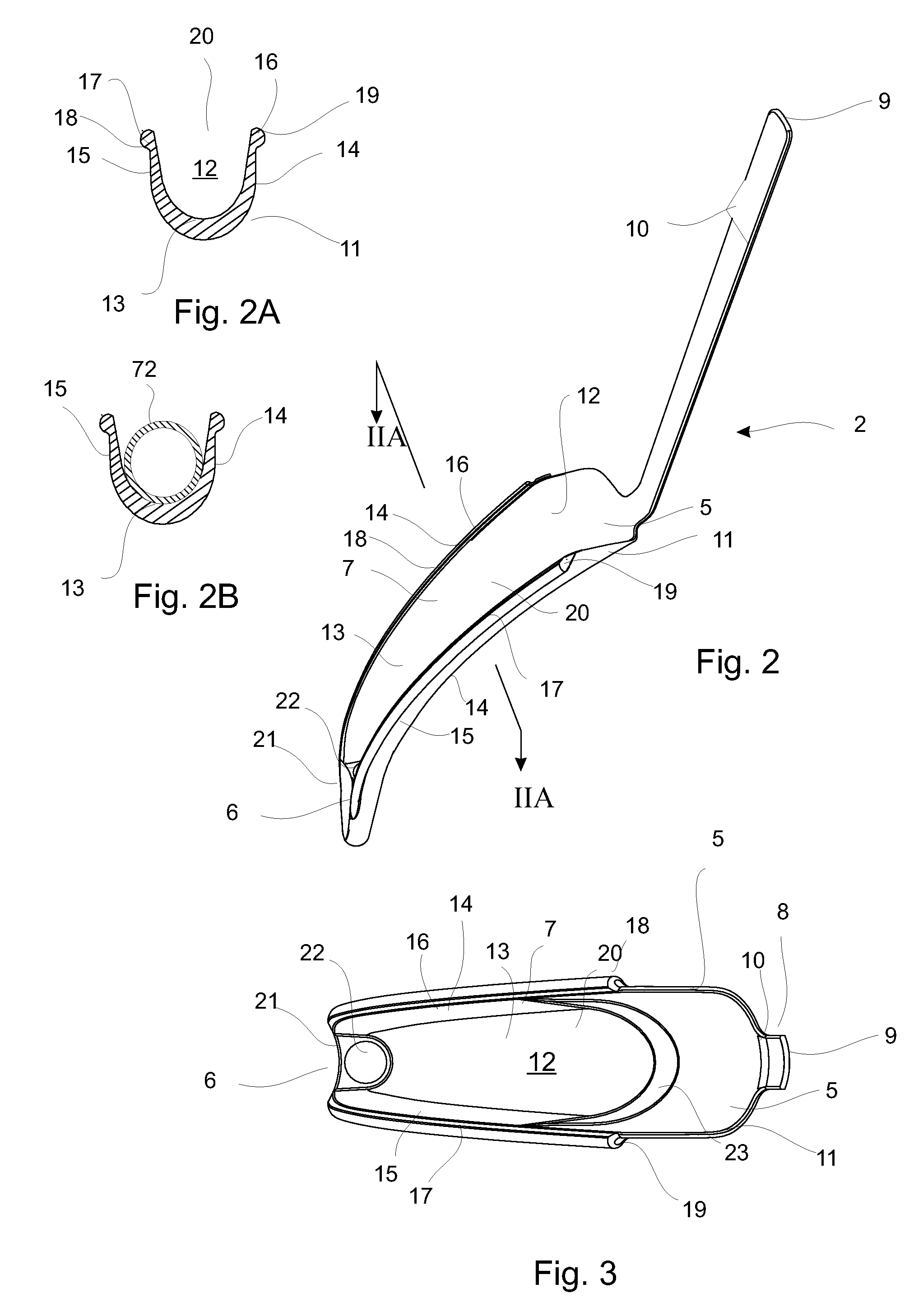
[0102]In FIG. 2 the dilator element 2 has a proximal end part 5, a distal tip part 6 and an intermediate part 7. The proximal end part 5 has a first coupling means 8, in the form of a protruding strap 8. The strap 8 protrudes towards a free end 9 having a protrusion 10.

[0103]As is clear from the cross sectional view taken along line II-II in FIG. 2A and 2B the wall 11 of the dilator element 2 has a U-shaped cross section, delimiting a dilator cavity or furrow at the proximal end part 5 and the intermediate part 7, which dilator cavity 12 has a U-shaped cross section. The U-shaped dilator cavity 12 has an interior bottom face 13 and opposite fa...


PUM


Abstract

A dilator assembly for percutaneous dilatational tracheostomy includes a dilator element having a wall and a proximal end part extending into a distal tip part via an intermediate part. The wall has a substantially U-shaped cross section defining a dilator opening. The assembly extends towards the distal tip part. The dilator assembly is part of a tracheostomy device. The device has a first branch for arranging inside the trachea, and a second branch co-operative with the first branch. The first branch has a first end and a receiving member while the opposing second end has a first coupling part. The second branch has a first end with a guide for a neck penetration member and an opposing second end with a second coupling part for coupling with the first coupling part of the first branch. The first and second branches are detachably coupled together at their respective second ends.

Description

[0001]This application is a 371 filing of International Patent Application PCT / EP2010 / 060746 filed Jul. 23, 2010.BACKGROUND[0002]The present invention relates to a dilator assembly adapted for percutaneous dilatational tracheostomy in a patient already having an endotracheal tube for ventilation, the dilator assembly comprising a dilator element having a wall and a proximal end part extending into a distal tip part via an intermediate part.[0003]A tracheostomy is a surgical procedure to create an opening through the neck into the trachea. A tube is placed through the opening to provide an airway and to remove secretions from the lungs. This tube is called a tracheostomy tube or trach tube.[0004]A tracheostomy is done in case of impaired respiratory function. This might be the case if for example a large object blocks the airway, the patient has an inherited abnormality of the larynx or trachea, has breathed in harmful material such as smoke, steam, or other toxic gases, suffers from...

Claims


Application Information

Patent Timeline
Patent Type & Authority Patents(United States)
IPC IPC(8): A61M16/00A61M16/04
CPCA61M16/0472
Inventor MARGOLIN, GREGORYKARLING, JONAS
Owner SAFETRACH
Why Eureka
Try Eureka