Cultivator with two rows of discs in direction of travel

a technology of discs and cultivators, which is applied in the direction of soil loosening devices, agriculture tools and machines, agriculture, etc., can solve the problems of difficult to get such a machine to run straight behind the tractor, difficulty in constructing type of machines, and difficulty in practice, so as to improve the ability of the machine to leave the level, improve the effect of machine function and no extra material costs

Active Publication Date: 2015-04-07
VADERSTAD HLDG
View PDF21 Cites 7 Cited by
  • Summary
  • Abstract
  • Description
  • Claims
  • Application Information

AI Technical Summary

Benefits of technology

[0010]Through moving the area where the direction of the discs is changed to in line with the tractor's wheel tracks the machine can be brought to give a better result as regards the condition of the soil surface behind the machine. This exploits the fact that the tractor's wheels virtually always make tracks where there is a smaller amount of soil to cultivate so that the function of the machine is improved. This is achieved through the soil level being lower due to the pressure exerted by the wheels. Through the device according to the invention the outcome is also that water does not remain standing in lower parts of the field, i.e. on both sides of a ridge or in the tractor's tracks. It is for reasons such as these that the farmer places great emphasis on getting fields level.
[0011]The area between the tractor wheels is normally approx. 1 m (internal dimensions), irrespective of the size of the tractor. This means that with the device according to the invention the point of change for both disc implement rows, where the reversed discs meet, is moved from the centre area of the machine to at least one half-meter in either direction. The points of change for the disc implement rows lie along a so-called dividing line that extends mainly parallel to the direction of travel of the machine. Through this displacement of the points of change / dividing line, the machine is still mainly X-shaped, the discs in the different rows, which tend to drive the machine to the side, still balance each other well. This way of improving the ability of the machine to leave level fields can without major difficulty be incorporated into machines and this can be done without any extra material costs.

Problems solved by technology

With a V-shaped arrangement it is easier to get a flat surface behind the machine, but it is difficult to get such a machine to run straight behind the tractor.
This functions in theory but in practice it is more complicated, for example because the discs of the different frame beams work in soil with different degrees of cultivation.
On the other hand, this type of machine is often more costly to construct since it can easily become more complicated.
Another problem with X-built disc implements is that it is difficult to get uniform excision in the centre while it is also difficult to get the soil level (flat) behind the machine, since a ridge or trough tends to form in the direction of travel of the machine.
It is naturally more difficult to get a good result behind the centre of the machine with regard to excision and levelness since the soil surface is elevated and more soil has to be handled here than at any other place in the machine.

Method used


Image

  • Cultivator with two rows of discs in direction of travel
  • Cultivator with two rows of discs in direction of travel
  • Cultivator with two rows of discs in direction of travel

Examples


first embodiment

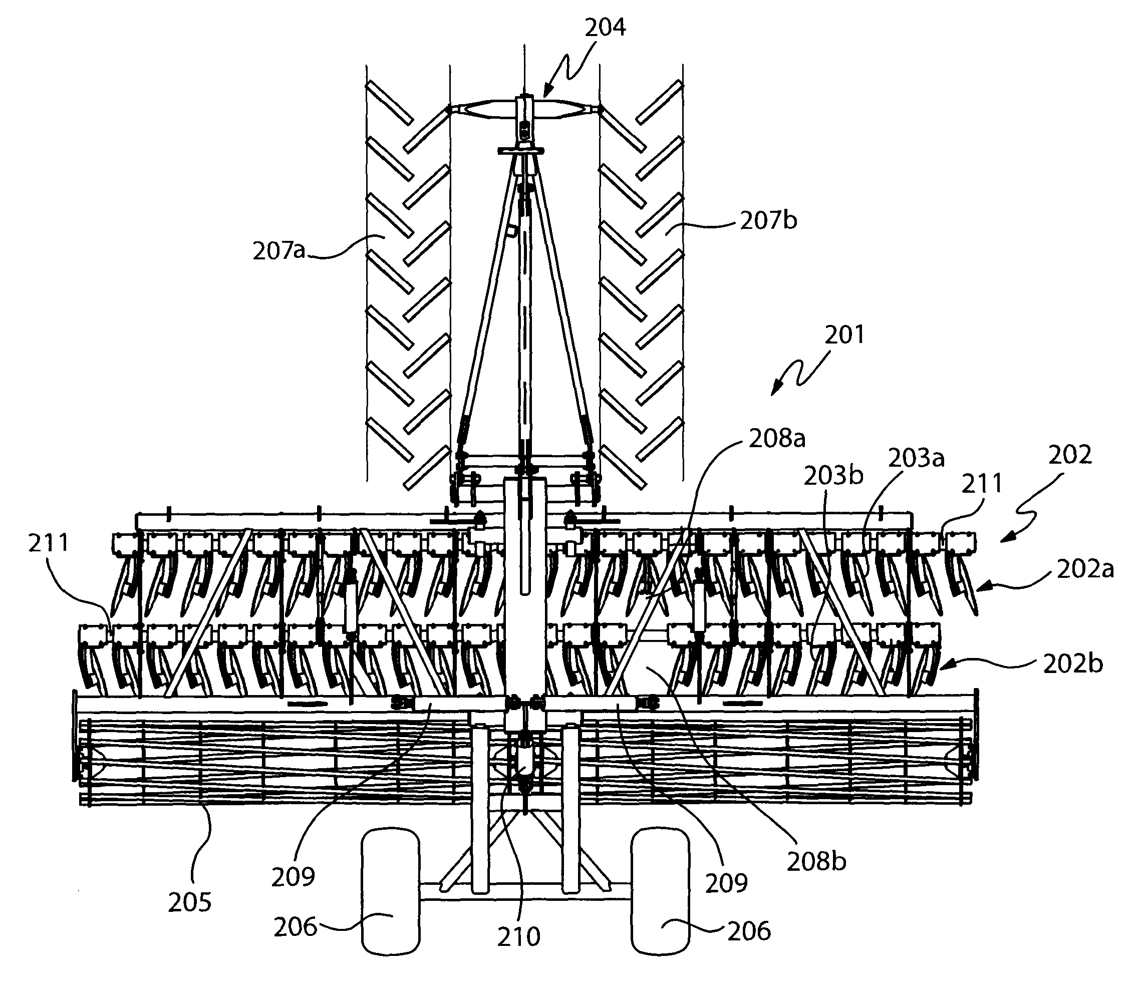
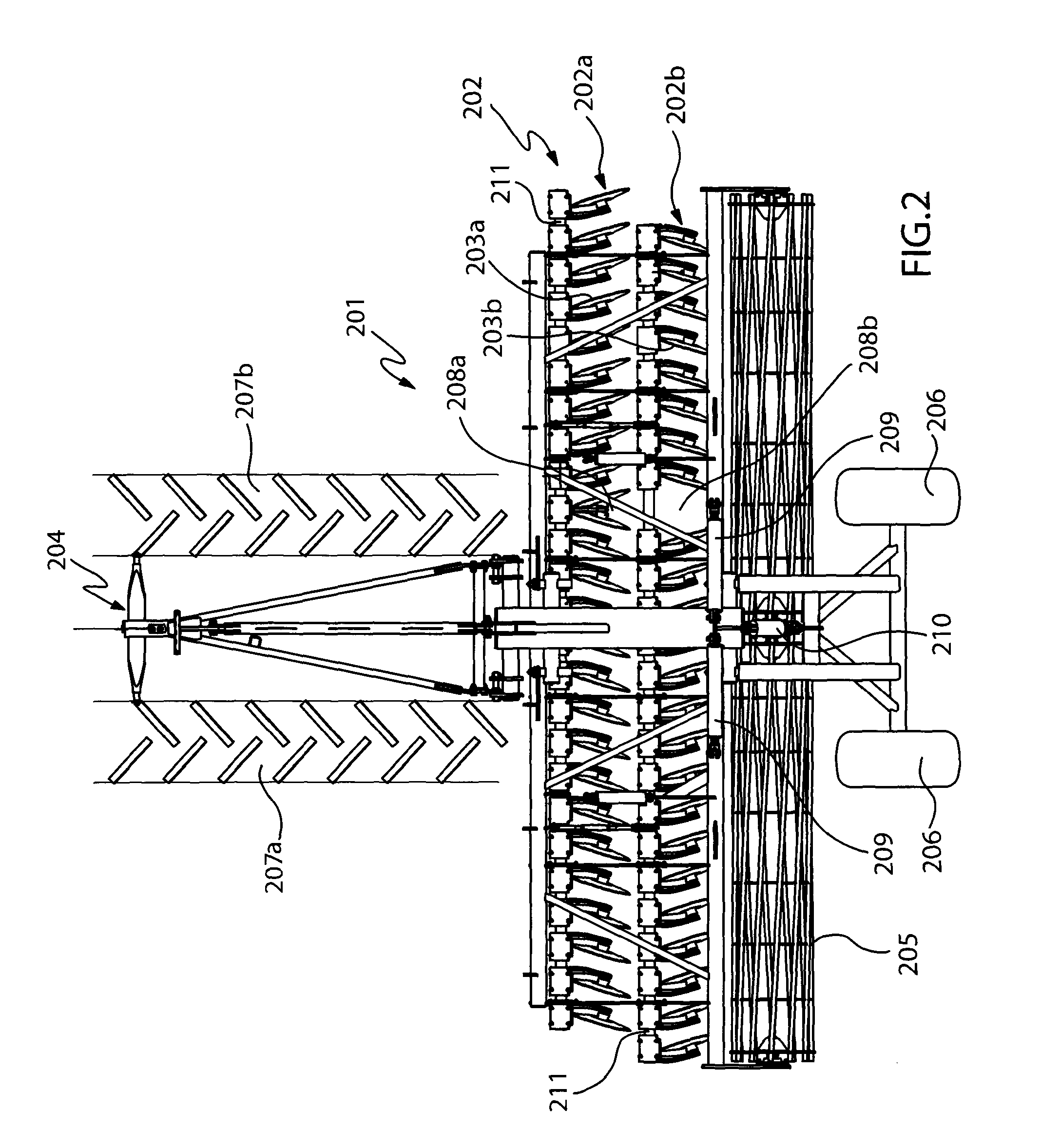
[0017]FIG. 2 illustrates an agricultural machine 201 with a device 202 according to the invention. The device 202 according to the invention comprises a frame structure with discs 203a and 203b arranged in X-shape, i.e. where the fore row 202a has discs 203a angled outwards towards the side of the machine and the rear row 202b has discs 202b, which are angled inwards from the side of the machine. This machine has rotatable frame beams. The discs 203a and 203b in the disc implement rows 202a and 202b resp. are suspended in frame beams with rubber elements in order to be able to recoil for example on impacts with stones. This agricultural machine 201 is intended for soil cultivation and comprises in addition to the device according to the invention a towing device 204, which can be coupled to a draught vehicle, such as a not shown tractor, a ribbed roller 205 for consolidation and working depth control arranged behind the discs 203a, 203b and wheels 206 for transport. This machine 201...

second embodiment

[0019]FIGS. 3a and 3b show an agricultural machine 301 with a device 304 according to the invention. This diagram shows soil cultivating fore discs 302a, which are mounted on arms which in their turn are recoilably mounted on frame beams 303. The discs 302b on the rear row are visible. Other details have been omitted for the sake of clarity. In order to clarify the device 304 according to the invention, the disc implements 302a and 302b in FIG. 3b have been lifted up from the soil surface to a transport position in order to more clearly show the profile of the soil surface. In this alternative the frame beams are not rotatable. The disc implement rows 302a and 302b of the agricultural machine 301 can be raised and lowered at altered working depth or raised to an appropriate clearance height for turning in the field or for road transport. Both disc implement rows 304a and 304b, which turn, i.e. change orientation, at the point of change 304c, are arranged behind each other in the dir...


PUM


Abstract

An agricultural machine (101; 201; 301) comprising two mainly parallel, in the direction of travel, cross-running disc implement rows (102a, 102c; 202a, 202b; 304a, 304b), wherein the orientation of the disc implements (102b, 102d; 203a, 203b; 302a, 302b) contained in the mentioned disc implement rows is arranged so that the fore row (102a; 202a; 304a) has disc implements that are mounted on a frame beam (110; 211; 303) and that are angled outwards and backwards towards the sides of the machine and in a dividing line mainly parallel to the direction of travel of the machine form a first point of change (208a, 304c), and the rear row (102c, 202b; 304b) has disc implements (102d; 203b; 302b) that are mounted on a frame beam (110; 211; 303) and that are angled inwards and backwards from the sides of the machine and in the dividing line form a second point of change (208b, 304a), wherein the fore row is adapted to throw soil from the first point of change outwards towards the sides of the machine and the other row is adapted to throw soil from the sides of the machine inwards towards the second point of change. The dividing line with the first point of change (208a, 304c), and with the second point of change (208b, 304) is arranged at a predetermined distance from the centre line of the machine (101; 201; 301) across the direction of travel.

Description

[0001]The present invention refers to a device at an agricultural machine comprising one frame structure with two mainly parallel, in the direction of travel cross-running disc implement rows.FIELD OF THE INVENTION[0002]For a long time different forms of disc implement have been produced for soil cultivation. A disc implement has oblique discs to cultivate the soil. Some types of machine only have discs as working members, which are commonly orientated on a fore and a rear frame beam. Other machines can have discs on two rows arranged within a combination machine that while the machine is cultivating the soil with discs are designed for other tasks, for example deep loosening of the soil or simultaneous sowing.[0003]The frame beams can be obliquely positioned and freely rotatable. The discs there can be rigidly connected with the frame beams. Another type of machine has two parallel carrying frame beams and discs that are mounted on arms, where every arm bears one or two discs and, ...

Claims


Application Information

Patent Timeline
Patent Type & Authority Patents(United States)
IPC IPC(8): A01B5/00A01B21/08A01B23/04
CPCA01B21/08A01B23/046
Inventor STARK, CRISTER
Owner VADERSTAD HLDG
Why Eureka
Try Eureka