Liquid ejecting head, liquid ejecting apparatus

a liquid ejector and liquid ejector technology, applied in the direction of printing, inking apparatus, etc., can solve the problems of failure of the liquid ejector to fully remove difficulty in completely removing the adhesive inside the flow path, so as to reduce the clogging of the nozzl

Active Publication Date: 2015-04-07
SEIKO EPSON CORP
View PDF2 Cites 0 Cited by
  • Summary
  • Abstract
  • Description
  • Claims
  • Application Information

AI Technical Summary

Benefits of technology

[0008]An advantage of some aspects of the invention is that the liquid ejecting head capable of reducing the failure in ejection due to nozzle clogging and the liquid ejecting apparatus having the same are provided.
[0010]In the above configuration, an adhesive that bonds the nozzle plate and the communication plate may flow out from between the substrates and creep up along the edge lines inside the communication hole. However, when the adhesive creeps up along the edge lines and reaches the flow path forming substrate, the adhesive is blocked by the surface of the flow path forming substrate close to the communication plate, since the edge lines of the communication hole at the surface close to the flow path forming substrate are covered with the flow path forming substrate on the bottom surface that defines the narrowed portion of the pressure chamber. The blocked adhesive merges with the adhesive which bonds the flow path forming substrate and the communication plate, and integrally cures. It is known that the cured adhesive tends to be peeled off at the edge portion. Accordingly, the adhesive is prevented from being peeled off at the edge portion by integrally curing the adhesive inside the flow path. By avoiding the edge portion from being formed, the risk that the adhesive is peeled off inside the flow path can be reduced, thereby reducing nozzle clogging caused by the peeled adhesive. In addition, since it is not necessary to consider the prevention of the adhesive from creeping up inside the flow path, the need of precisely designing the form of flow path depending on the applied amount of adhesive can be eliminated.
[0011]According to the above aspect of the invention, the communication hole may have a second opening that is open to the surface close to the flow path forming substrate and a third opening that is open to a surface close to the nozzle plate, and a narrow flow path may be formed at a position between the second opening and the third opening of the communication hole, the narrow flow path having an inner width in the first direction which is smaller than an inner width of either the second opening or the third opening. In the above configuration, the wall between the adjacent communication holes becomes thin when the inner width of the communication hole in the first direction is increased in relation to the narrowed portion of the flow path forming substrate. As a result, a problem of crosstalk may occur. When one of the adjacent communication holes deforms, another communication hole may deform due to the crosstalk, which effects on the ejection timing of the liquid. In order to avoid such a problem, the narrow flow path is provided in the communication hole. Accordingly, in the direction in which the communication hole extends, the thickness of the wall that defines the communication hole varies in the first direction, thereby preventing deformation of the wall. As a consequence, it is possible to prevent the crosstalk. Moreover, the prevention of crosstalk enables the communication holes to be closely arranged. Accordingly, the nozzles can be arranged with high density.
[0012]The communication hole may have a resistance adjustment portion having an inner width in the second direction which is larger than an inner width of the second opening in the second direction, the second direction being perpendicular to the first direction. In the above configuration, the resistance adjustment portion provided inside the communication hole may increase the flow path resistance in the flow path extending from the pressure chamber to the communication hole. In order to avoid such a problem, the communication hole may have the resistance adjustment portion having an increased inner width in the second direction at a portion in the flow path close to the nozzle plate, thereby reducing the flow path resistance.
[0013]The communication hole may be formed in a rectangular shape having four edge lines. Accordingly, it is possible to form the communication hole with ease by etching process or the like.
[0016]In the above configuration, a step is formed in the communication hole on the edge line having the end which is not covered with the surface of the flow path forming substrate close to the communication plate, so that the edge line has a discontinuity. Accordingly, the step can prevent the adhesive from creeping up toward the flow path forming substrate, thereby reducing nozzle clogging caused by the peeled adhesive.

Problems solved by technology

When the liquid ejecting head is actuated, the adhesive may be peeled off inside the flow path, leading to nozzle clogging.
The nozzle clogging causes ejection failure of the liquid ejecting head.
It has been difficult to completely remove the adhesive inside the flow path when the adhesive is cleaned by using a solvent.
Such precise designing of dimensions may limit the design freedom of the flow path.
As a result, a problem of crosstalk may occur.

Method used


Image

  • Liquid ejecting head, liquid ejecting apparatus
  • Liquid ejecting head, liquid ejecting apparatus
  • Liquid ejecting head, liquid ejecting apparatus

Examples


first embodiment

1. First Embodiment

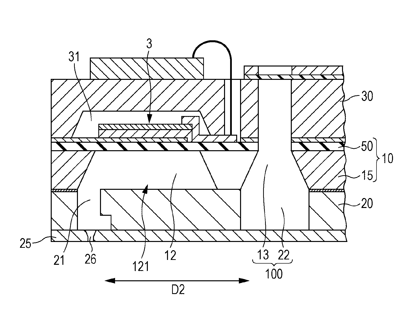
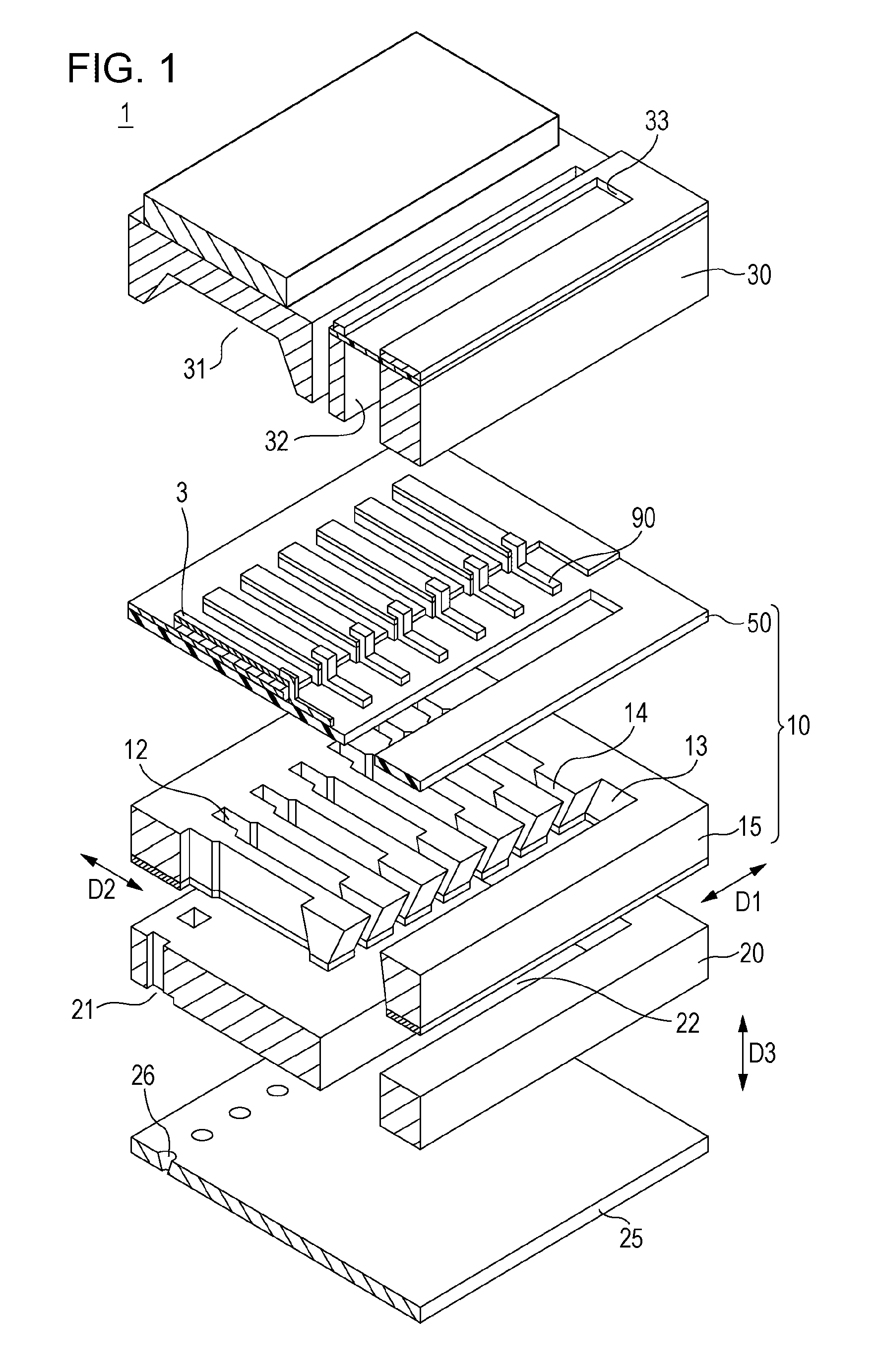
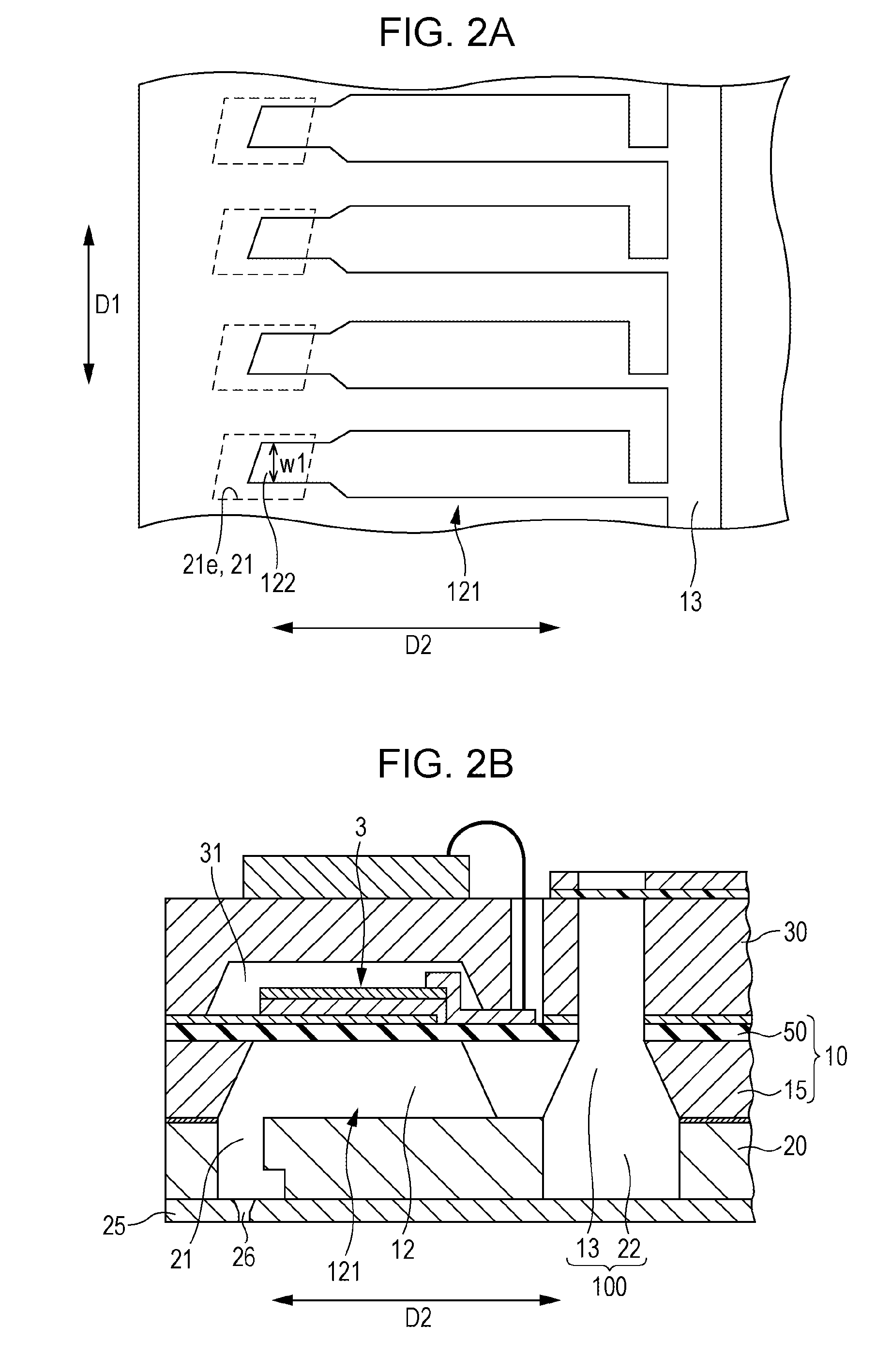
[0026]FIG. 1 is an exploded perspective view of a liquid ejecting head 1 according to a first embodiment of the invention. FIGS. 2A and 2B are views which show a positional relationship between a pressure chamber and a communication hole.

[0027]The liquid ejecting head 1 according to this embodiment is used as part of a liquid ejecting apparatus that ejects a liquid such as ink. As shown in FIG. 1, the liquid ejecting head 1 includes a nozzle plate 25, a communication plate 20, a flow path forming substrate 10 and a sealing substrate 30. In the figures, for better understanding of the configuration of the flow path forming substrate 10, the flow path forming substrate 10 is shown as being separated into two parts.

[0028]The liquid ejecting head 1 is composed of at least the flow path forming substrate 10, the communication plate 20 and the nozzle plate 25, which are bonded to each other by using an adhesive. When those substrates are bonded to each other by using an...

second embodiment

2. Second Embodiment

[0051]FIGS. 7A and 7B are views which show a configuration of the communication hole 21 and the pressure chamber 12 according to the second embodiment. In the second embodiment, instead of all the ends of the edge lines, only some of the ends of the edge lines at the second opening 21e are covered with the bottom surface 101 of the flow path forming substrate 10. On the edge line having the end which is not covered with the flow path forming substrate 10, a step is formed at a position between the second opening 21e and the third opening 21f so that the edge line has a discontinuity. Since the edge line has the discontinuity, the adhesive can be prevented from creeping up along the edge line.

[0052]As shown in FIG. 7A, the communication hole 21 is formed by a rectangular hole which extends in the third direction D3. The hole is surrounded by the walls which intersect at an acute or obtuse angle. Four edge lines 21a to 21d are formed at intersections of the walls. ...


PUM


Abstract

A liquid ejecting head includes a nozzle plate, a flow path forming substrate, and a communication plate between the nozzle plate and the substrate and having a communication hole connecting a nozzle and a first opening of a pressure chamber. The first opening extends in a direction perpendicular to an arrangement direction of the pressure chambers. The first opening has a narrowed portion close to the communication hole. The communication hole has at least three edge lines which extend in a penetration direction. The communication plate is bonded to the substrate such that the ends of the edge lines at a surface close to the substrate are covered with the substrate that defines the narrowed portion on a surface close to the communication plate.

Description

BACKGROUND[0001]1. Technical Field[0002]The present invention relates to liquid ejecting heads that eject liquid through nozzles, and more specifically to liquid ejecting heads in which liquid flow paths are formed by bonding a plurality of substrates to each other.[0003]2. Related Art[0004]Liquid ejecting heads that eject a liquid such as ink through nozzles are known. A liquid ejecting head includes piezoelectric elements that deform in response to the applied voltage, flow paths through which liquid flows and nozzles that communicate with the flow paths and allow the liquid to be ejected through the nozzles. Accordingly, when a pressure is generated in the flow paths due to deformation of the piezoelectric elements, the pressure causes the liquid flowing through the flow paths to be ejected through the nozzle openings. Such a liquid ejecting head is used, for example, as part of the printing apparatus or the like.[0005]Further, liquid ejecting heads in which flow paths are formed...

Claims


Application Information

Patent Timeline
Patent Type & Authority Patents(United States)
IPC IPC(8): B41J2/14B41J2/16B41J2/045
CPCB41J2/14233B41J2202/11B41J2202/20
Inventor FUKUZAWA, YUMAOWAKI, HIROSHIGE
Owner SEIKO EPSON CORP
Why Eureka
Try Eureka