Rotary speed-change transmission

a rotary transmission and speed-change technology, applied in the field of transmission, can solve the problems of high construction effort and device technical complexity, unsuitable heavy machinery, and high transmission costs, and achieve high transmission ratio, compact design, and high torque.

Inactive Publication Date: 2015-04-07
SMS MEER
View PDF4 Cites 14 Cited by
  • Summary
  • Abstract
  • Description
  • Claims
  • Application Information

AI Technical Summary

Benefits of technology

[0008]It is therefore an object of the present invention to provide an improved rotary speed-change transmission.
[0020]With the transmission described here, it is possible to transmit high torques at high transmission ratios. With the proposed approach, it is advantageous in particular that a rolling movement sequence of the transmission elements is made possible in the transmission of torque, so that no mentionable wear occurs even in the transmission of high torques.
[0021]It is also very advantageous that no damage to the components of the transmission need be feared even under a sudden load.
[0022]Another advantage of the proposed approach is that the transmission has a very compact design.
[0023]The concept proposed according to the invention creates in particular the great advantage that it yields a simple and inexpensive design because no additional bearing elements need be provided for rotatably supporting the transmission elements. Instead this achieves the result that through the preferred symmetrical embodiment of the transmission elements utilizing the wave structure, i.e., in particular due to the symmetrical arrangement of the rollers for the drive, for support and for output, there is no external reactive torque when a load is applied to the transmission. The shaft with the rollers mounted on it is namely more or less spanned and centered between the edge of the input element, of the output recesses, and of the guides in the retaining rings. Therefore it is not necessary to have additional bearings for the shaft with its rollers. Only the above-described axial stops in the form of stop washers or spur disks limit axial mobility and / or axial play, preferably positioned axially between the guide rollers and the output rollers.

Problems solved by technology

The above-described known designs of transmissions always fulfill these requirements only partially and in particular the transmissible torque is usually very limited so that the above-described solutions are not suitable for heavy machinery.
One disadvantage of these transmissions is that the construction effort and the technical complexity of the device are quite high and the transmissions are as a result expensive.

Method used


Image

  • Rotary speed-change transmission
  • Rotary speed-change transmission
  • Rotary speed-change transmission

Examples


Embodiment Construction

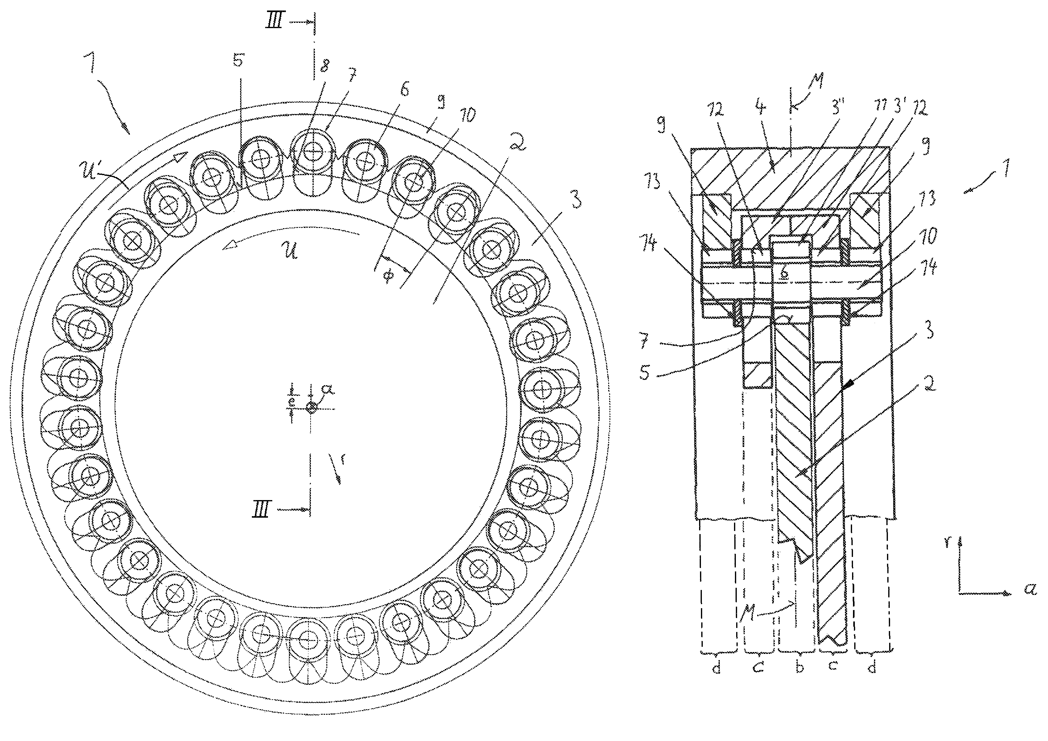
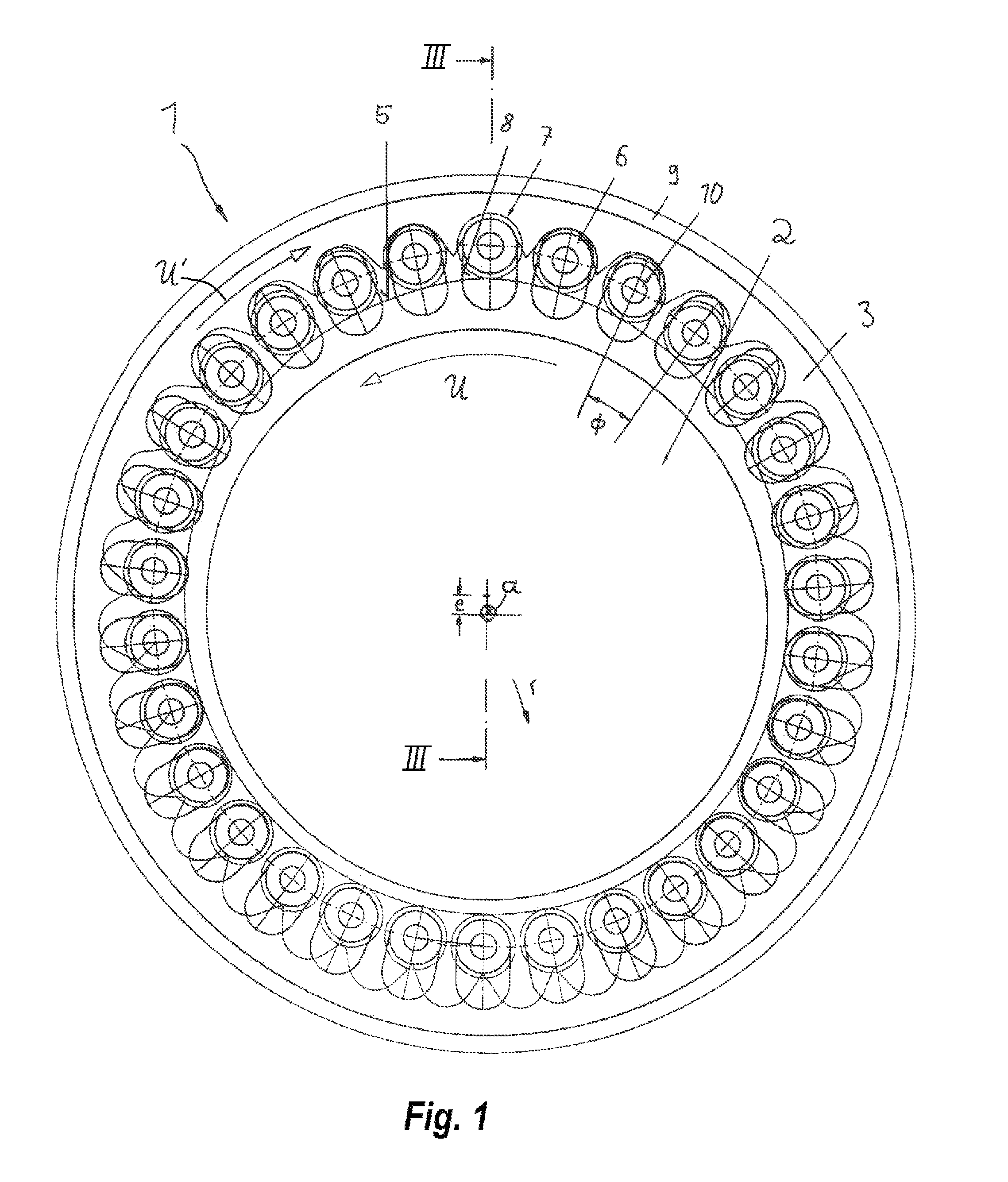
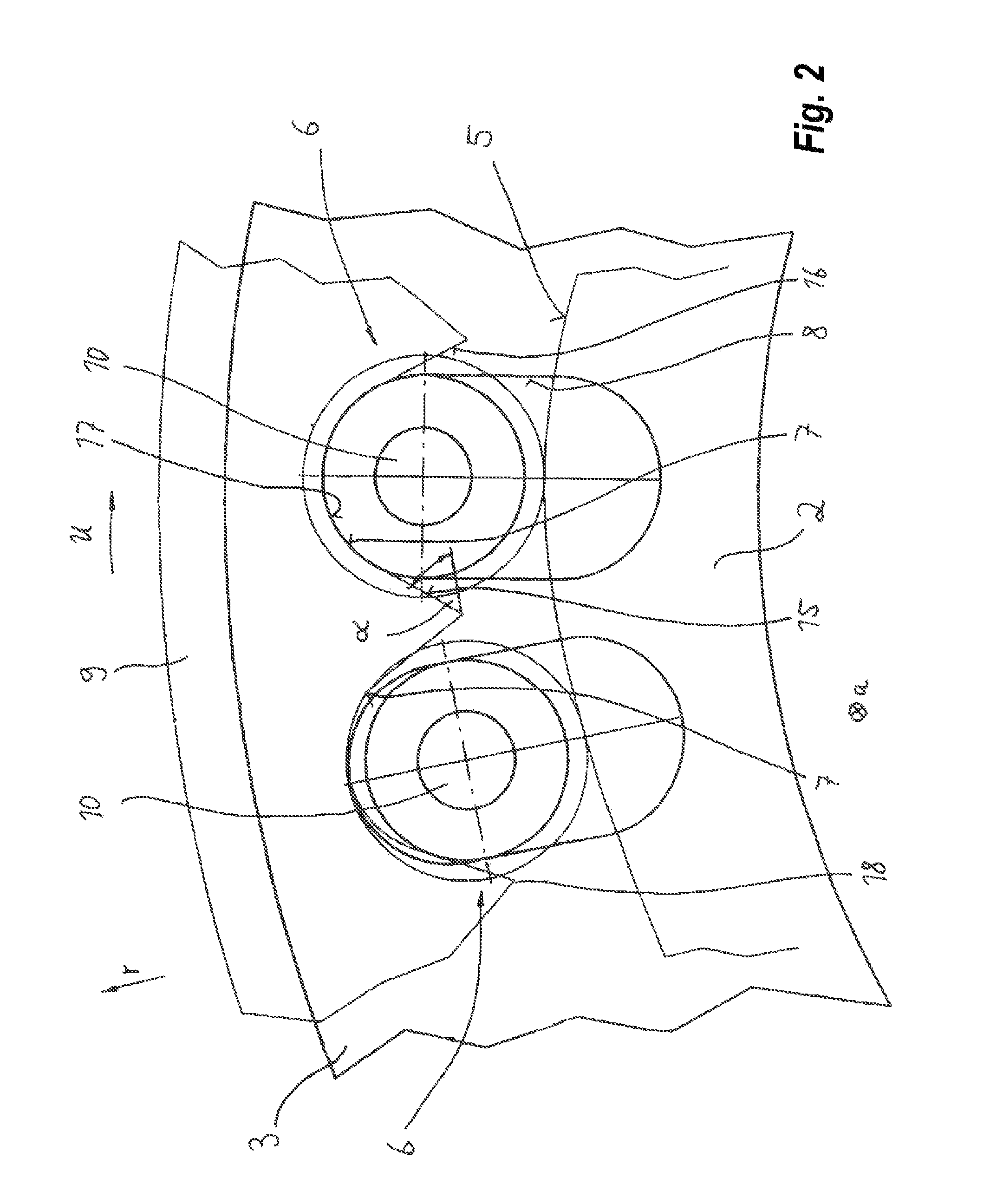
[0028]As seen in the drawing, a transmission 1 for use in heavy machinery for transmitting high torque at a high transmission ratio has a drive or input element 2 to which an unillustrated drive shaft can be fixed and a driven or output element 3 to which an unillustrated output shaft is also rotationally fixed. The input element 2 and the output element 3 rotate about a common axis a that here is perpendicular to the view planes of FIGS. 1 and 2.

[0029]The input element 2 is a disk and the output element 3 is largely annular. Both the input element 2 and the output element 3 are rotatably mounted in a normally nonrotating housing 4 (FIG. 3). Bearings that support them in the housing 4 are not shown and are standard.

[0030]The input element 2 has a radially outwardly directed peripheral edge surface 5 that is basically cylindrical serves as a guide for transmission elements 6 described in greater detail below. This guide surface 5 is offset upward in FIG. 1 by an eccentricity e to the...


PUM


Abstract

A transmission has a housing having a main axis with a retaining element fixed in the housing and forming a set having a predetermined number of radially extending and angularly equispaced guides. An output element rotatable in the housing about the axis is formed with an array having a number smaller than the predetermined number of radially inwardly open recesses axially adjacent the guides. An input element rotatable in the housing about the axis has a radial outer and generally circular peripheral surface centered on an axis radially offset from the main axis. Respective transmission elements radially displaceable in the guide grooves between inner and outer positions each have a shaft extending substantially parallel to the axis with a guide section engaged and radially shiftable in the respective guide groove, a driven section engageable in the recesses, and a drive section radially engageable with the input-element surface.

Description

FIELD OF THE INVENTION[0001]The present invention relates to a transmission. More particularly this invention concerns a torque-transmitting rotary transmission.BACKGROUND OF THE INVENTION[0002]The invention relates to a transmission for transmitting torque from a drive or input element to a driven or output element where the input element and the output element rotate about a common axis of rotation. The input element and the output element are rotatably mounted in a housing, and the input element has at least one radially outwardly directed peripheral surface engaging at least one drive section of a number of transmission elements. That the output element forms an array of a predetermined number of radially inwardly open recesses angularly equispaced about the axis and forming a contact surface for at least one driven section of the transmission elements. The transmission elements are radially displaceable in guides of at least one retaining element fixed in or on the housing. The...

Claims


Application Information

Patent Timeline
Patent Type & Authority Patents(United States)
IPC IPC(8): F16H1/32F16H25/06
CPCF16H25/06
Inventor WENGENROTH, VOLKER
Owner SMS MEER
Why Eureka
Try Eureka