Prosthetic heart valve having identifiers for aiding in radiographic positioning

a heart valve and identifier technology, applied in the field of pro, can solve the problems of difficult three-dimensional visual differentiation of the commissural posts from the rest of the valve prosthesis, and achieve the effect of improving the accuracy of the identifier and reducing the difficulty of the identifier

Active Publication Date: 2015-04-07
MEDTRONIC INC
View PDF656 Cites 41 Cited by
  • Summary
  • Abstract
  • Description
  • Claims
  • Application Information

AI Technical Summary

Benefits of technology

[0041]In some embodiments of the present invention, the openings that define the radiographic identifiers are shaped to be reflection-asymmetric along respective post axes that are generally parallel with a central longitudinal axis of the prosthesis when the posts assume their collapsed position. For example, the identifiers may be shaped as one or more reflection-asymmetric characters, such as numbers or letters of the alphabet, e.g., B, C, D, E, etc. The physician can thus readily identify the true orientation of the selected post that appears to be rotationally aligned with the selected native commissure. If the identifier on the selected post appears in the correct left-right orientation, the selected post is aligned in the desired position (1). If, on the other hand, the identifier appears as the mirror image of its correct left-right orientation, the selected post is incorrectly rotationally aligned in position (2). To correct the alignment, the physician may rotate the valve prosthesis approximately 60 degrees in either direction, thereby ensuring that one of the two other posts is now rotationally aligned in position (1).

Problems solved by technology

Without such identifiers, it is generally difficult to three-dimensionally visually distinguish the commissural posts from one another and from the rest of the valve prosthesis, because the radiographic imaging produces a two-dimensional representation of the three-dimensional valve prosthesis.

Method used


Image

  • Prosthetic heart valve having identifiers for aiding in radiographic positioning
  • Prosthetic heart valve having identifiers for aiding in radiographic positioning
  • Prosthetic heart valve having identifiers for aiding in radiographic positioning

Examples


Embodiment Construction

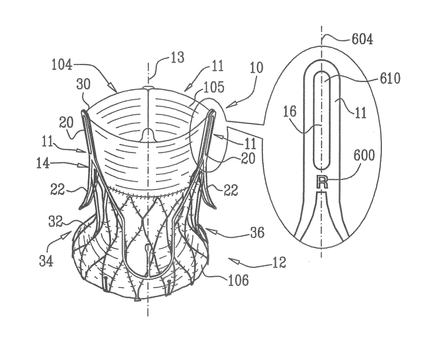
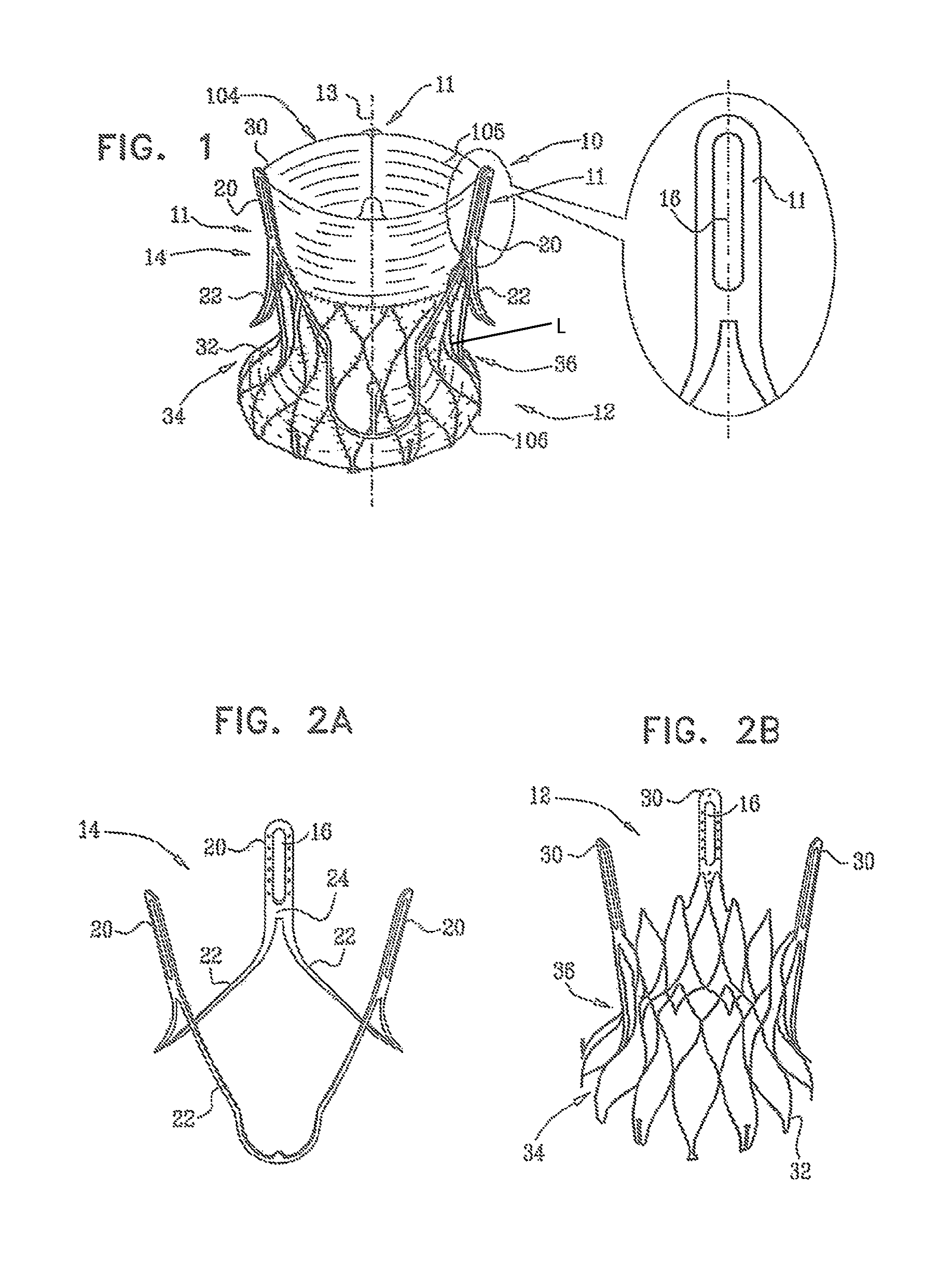
[0087]FIG. 1 is a schematic illustration of a fully-assembled valve prosthesis 10, in accordance with an embodiment of the present invention. Typically, valve prosthesis 10 comprises exactly three commissural posts 11, arranged circumferentially around a central longitudinal axis 13 of valve prosthesis 10. Valve prosthesis 10 further comprises a prosthetic distal valve 104 coupled to coupled to commissural posts 11. Valve 104 typically comprises a pliant material 105. Pliant material 105 of valve 104 is configured to collapse inwardly (i.e., towards central longitudinal axis 13) during diastole, in order to inhibit retrograde blood flow, and to open outwardly during systole, to allow blood flow through the prosthesis. For some applications, valve prosthesis 10 comprises a collapsible inner support structure 12 that serves as a proximal fixation member, and a collapsible outer support structure 14 that serves as a distal fixation member.

[0088]One or more (e.g., all) of commissural po...


PUM


Abstract

A prosthetic heart valve having identifiers for aiding in radiographic positioning is described.

Description

[0001]This application claims the benefit under 35 U.S.C. §119(c) of U.S. patent application Ser. No. 61 / 192,201, filed Sep. 15, 2008, which is herein incorporated by reference in its entirety. The present invention relates generally to prosthetic heart valves, and specifically to techniques for accurately positioning such valves during implantation procedures.FIELD OF THE INVENTIONBackground of the Invention[0002]Aortic valve replacement in patients with severe valve disease is a common surgical procedure. The replacement is conventionally performed by open heart surgery, in which the heart is usually arrested and the patient is placed on a heart bypass machine. In recent years, prosthetic heart valves have been developed which are implanted using minimally invasive procedures such as transapical or percutaneous approaches. These methods involve compressing the prosthesis radially to reduce its diameter, inserting the prosthesis into a delivery tool, such as a catheter, and advanci...

Claims


Application Information

Patent Timeline
Patent Type & Authority Patents(United States)
IPC IPC(8): A61F2/24
CPCA61F2/2418A61F2/2436A61F2250/0098A61F2220/0016A61F2220/0075A61F2230/005A61F2230/0054A61F2230/008A61B34/20A61B2090/376A61F2/2427A61F2250/0097
Inventor TUVAL, YOSSIBENARY, RAPHAEL
Owner MEDTRONIC INC
Why Eureka
Try Eureka