Distributed fibre optic sensing for event detection

a technology of event detection and distributed fibre optics, applied in the field of methods and apparatuses, can solve problems such as full coherence, and achieve the effect of reducing coupling

Active Publication Date: 2015-04-07
VIAVI SOLUTIONS INC
View PDF28 Cites 18 Cited by
  • Summary
  • Abstract
  • Description
  • Claims
  • Application Information

AI Technical Summary

Benefits of technology

[0043]Further aspects are i) the installation of the fibre in such a way as to minimise the coupling between polarisation eigenmodes; ii) the separate detection of the backscattered signals from each of the eigenmodes; iii) the ratioing of the two DEL disturbance signals to provide the direction from which the disturbance originated, with a 180° ambiguity; and iv) the use of D-fibre, which allows the identification, in space, of the directions of the birefringence axes of the fibre, and thus also of the origin of the disturbance.

Problems solved by technology

The optical pulses are partially coherent pulses such that self-interference occurs, but are not fully coherent such that the power in the optical pulse is not heavily constrained by Brillouin scattering.

Method used


Image

  • Distributed fibre optic sensing for event detection
  • Distributed fibre optic sensing for event detection
  • Distributed fibre optic sensing for event detection

Examples


Embodiment Construction

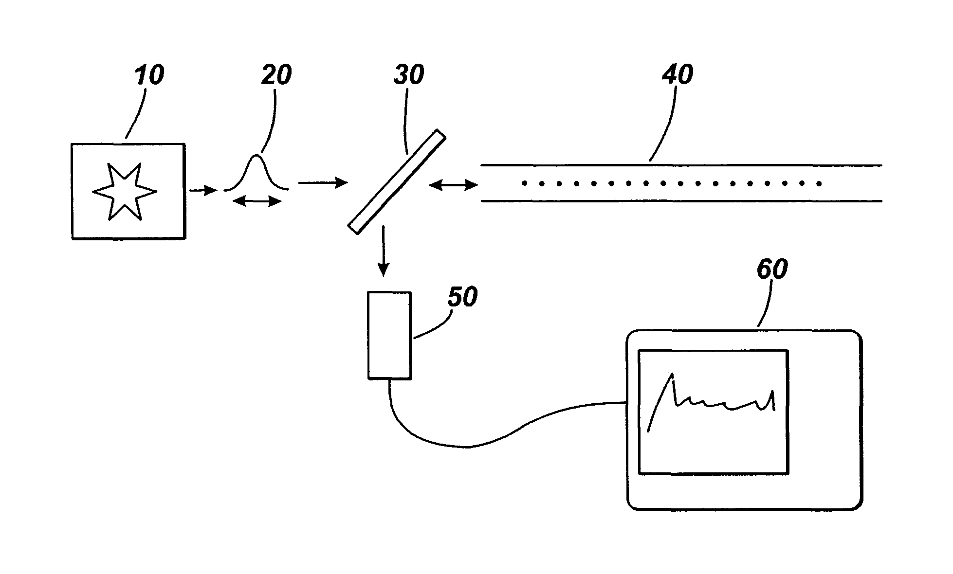
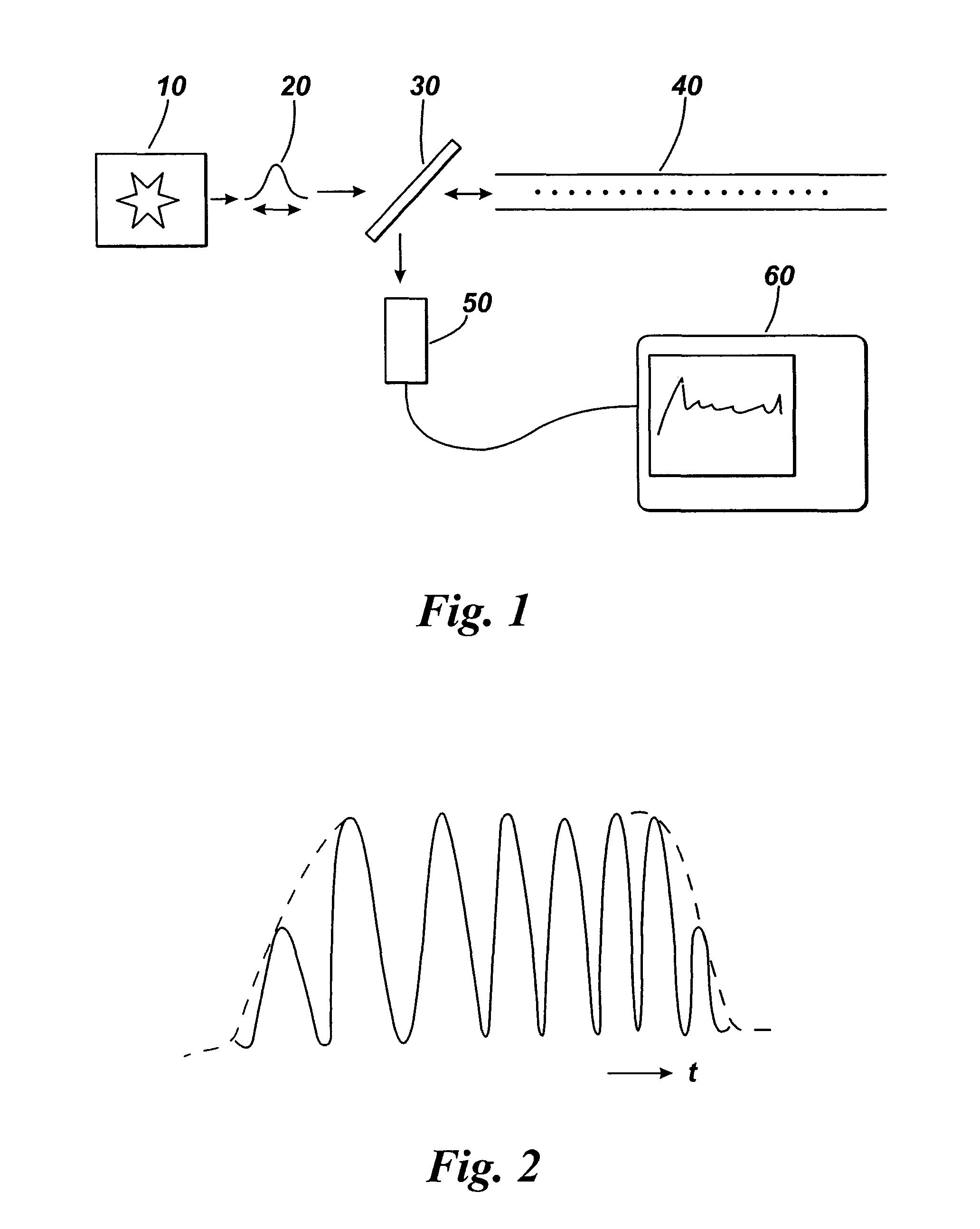
[0059]FIG. 1 illustrates an arrangement for partially coherent reflectometry. The arrangement includes a laser 10 or other optical source arranged to emit coherent light. The laser 10 is arranged to generate optical pulses 20 which are launched into an optical fibre 40. Between the laser 10 and fibre 40 is a beamsplitter 30 or optical circulator. The beamsplitter or optical circulator allows light from the laser to pass into the fibre. If a beamplitter is used, a small amount of the input pulse can be tapped off for monitoring. The light is launched down the optical fibre 40 and some of the light is backscattered or reflected along the length of the fibre. Rayleigh backscattering occurs along the length of the fibre at scattering centres such as atoms, molecules, and other features of a size much smaller than the wavelength of the light. For example, the glass from which the core of the fibre is produced may be considered to be analogous to a fluid in which the atoms and molecules a...


PUM


Abstract

A fiber optic sensing method and apparatus for determining location and direction information of disturbances occurring in the environment of a sensor optical fiber are provided. The method comprises launching optical pulses into at least one polarisation eigenmode of a polarisation maintaining fiber as the sensor optical fiber, detecting temporal speckle patterns of light backscattered from the at least one polarisation eigenmode of the fiber, comparing the temporal speckle patterns to determine the location and direction information of a disturbance in the environment of the sensor optical fiber. The location information may be a distance along the fiber, and the direction information may be a direction radially from the axis of the fiber. The apparatus or instrument may be used to detect disturbance over long distances such as pipes, pipelines, or wells. Other applications include detecting intruders entering a controlled area.

Description

CROSS REFERENCE TO RELATED APPLICATIONS[0001]This application is a national phase application under 35 U.S.C. §371 of International Application No. PCT / GB2009 / 002650, filed on Nov. 12, 2009, which claims priority to and the benefit of U.K. Patent Application No. 0820658.3, filed on Nov. 12, 2008, the entire disclosures of each of which are incorporated by reference herein.TECHNICAL FIELD[0002]The present invention relates to methods and apparatus for detecting the location of disturbances in the environment of an optical fibre. In particular, the present invention relates to a method and apparatus for detecting the direction of the disturbance relative to the optical fibre.BACKGROUND ART[0003]Optical Time-Domain Reflectometry (OTDR) is a technique for analysing optical fibres as well as other optical components, and is commonly used in the telecommunications industry for analysing breaks in fibre. The technique consists of sending a series of optical pulses along the fibre under tes...

Claims


Application Information

Patent Timeline
Patent Type & Authority Patents(United States)
IPC IPC(8): G02B6/00G01D5/353G01M11/00
CPCG01M11/3181G01D5/353G01M11/3109G01D5/35358
Inventor ROGERS, ALAN JOHN
Owner VIAVI SOLUTIONS INC
Why Eureka
Try Eureka