Scan chain configuration for test-per-clock based on circuit topology

a circuit topology and clock technology, applied in the field of circuit testing technology, can solve the problems of increasing the time for data loading and unloading operations, the clock is usually kept slower, and the test-per-clock scheme, though well developed and widely adopted, is not very efficient in testing tim

Active Publication Date: 2015-04-14
SIEMENS PROD LIFECYCLE MANAGEMENT SOFTWARE INC
View PDF6 Cites 1 Cited by
  • Summary
  • Abstract
  • Description
  • Claims
  • Application Information

AI Technical Summary

Problems solved by technology

Moreover, in part due to power concerns, the shifting clock is usually kept slower than the clock for the circuit's normal operation.
This further increases time for the data loading and unloading operations.
The above two examples demonstrate that the test-per-scan scheme, though well developed and widely adopted, is not very efficient with respect to testing time.
However, the conventional test-per-clock BIST scheme may have a problem on power consumption.
This can lead to excessive circuit toggling and thus power dissipation.

Method used


Image

  • Scan chain configuration for test-per-clock based on circuit topology
  • Scan chain configuration for test-per-clock based on circuit topology
  • Scan chain configuration for test-per-clock based on circuit topology

Examples


Embodiment Construction

[0021]Various aspects of the present invention relate to generating scan chain configurations for test-per-clock based on circuit topology. In the following description, numerous details are set forth for the purpose of explanation. However, one of ordinary skill in the art will realize that the invention may be practiced without the use of these specific details. In other instances, well-known features have not been described in details to avoid obscuring the present invention.

[0022]Some of the techniques described herein can be implemented in software instructions stored on a computer-readable medium, software instructions executed on a computer, or some combination of both. Some of the disclosed techniques, for example, can be implemented as part of an electronic design automation (EDA) tool. Such methods can be executed on a single computer or on networked computers.

[0023]The detailed description of a method or a device sometimes uses terms like “generate” and “determine” to des...


PUM


Abstract

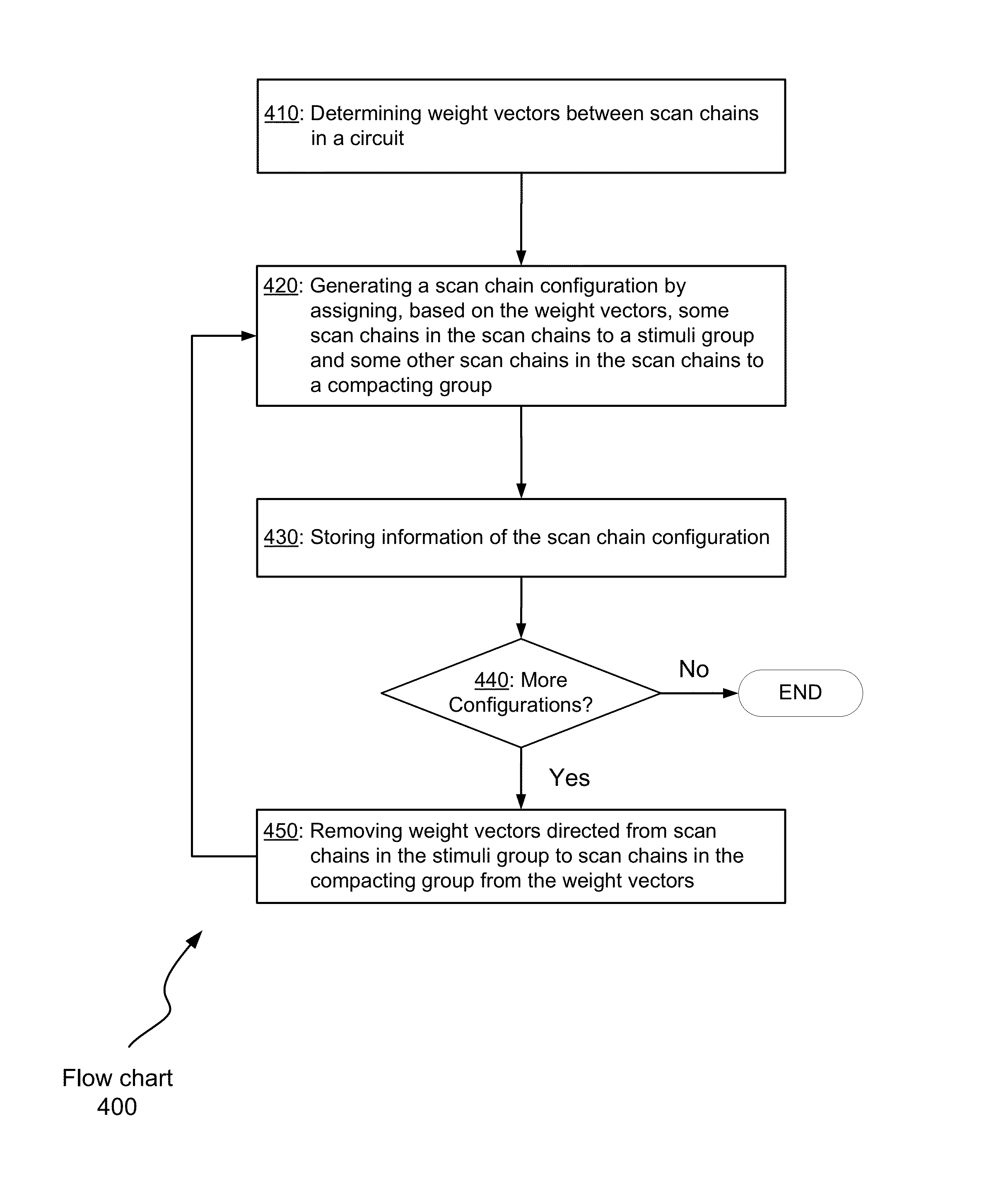
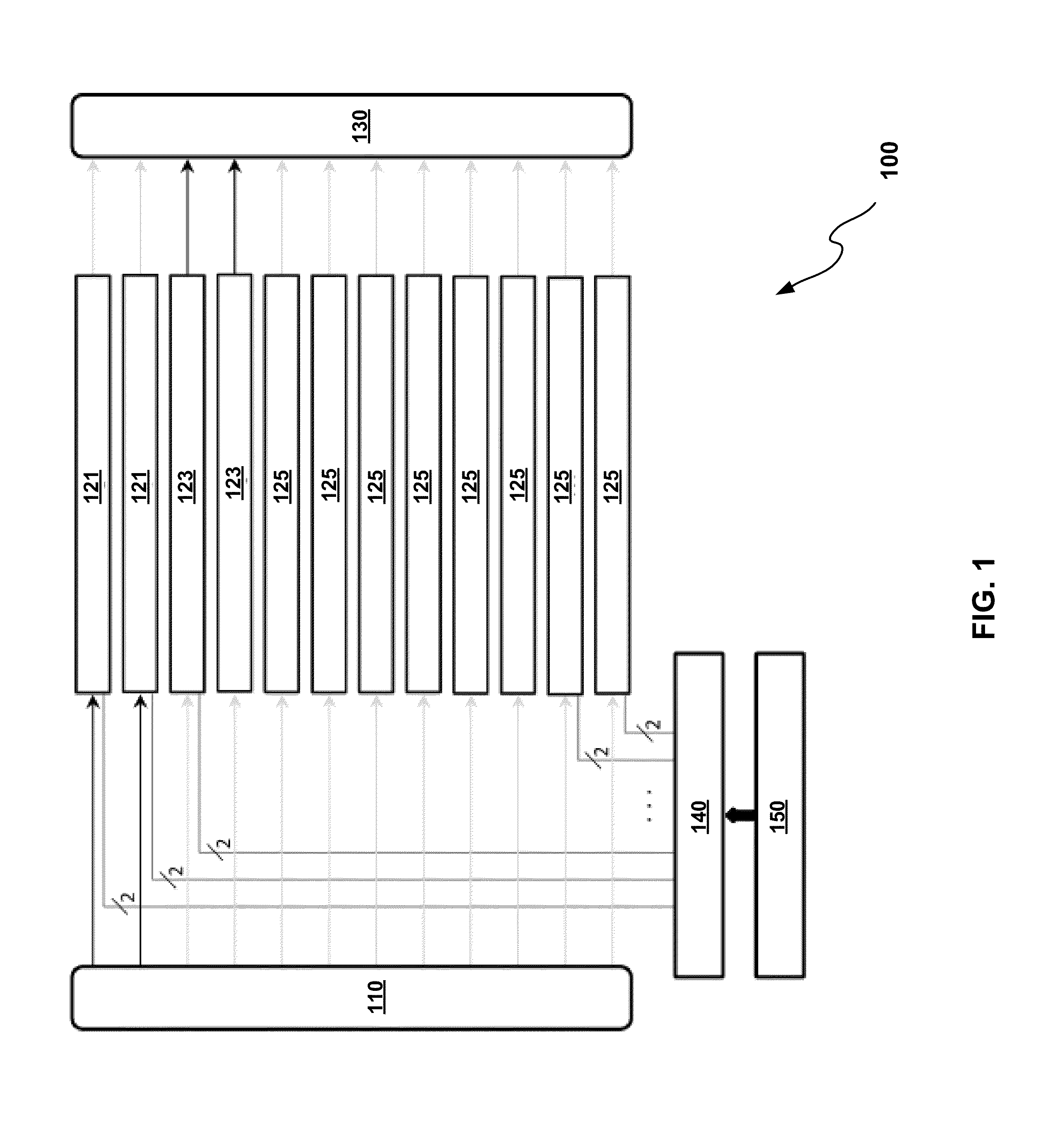
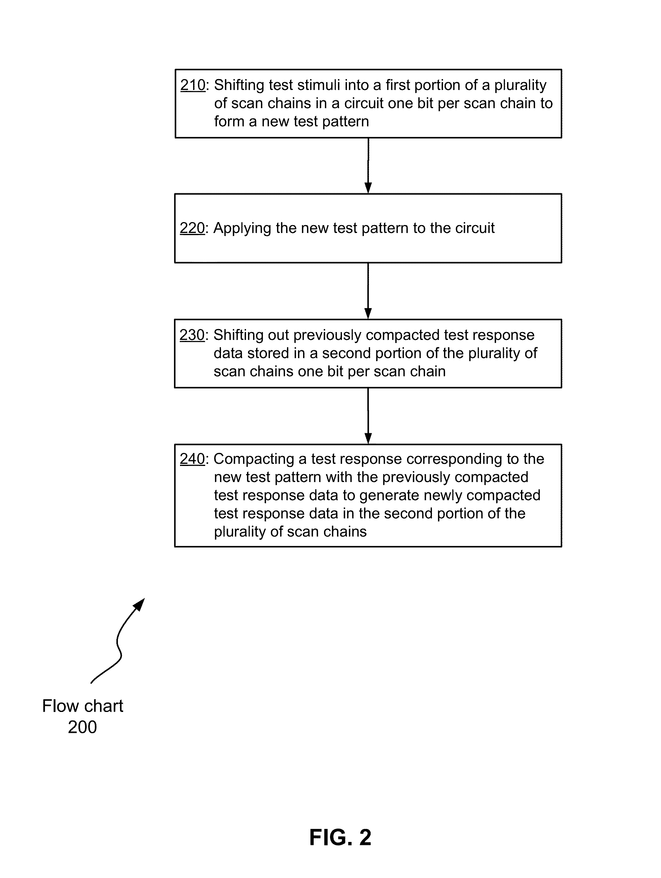
Aspects of the invention relate to generating scan chain configurations for test-per-clock based on circuit topology. With various implementations of the invention, weight vectors between scan chains in a circuit are first determined. Based on the weight vectors, a scan chain configuration is generated by assigning some scan chains in the scan chains to a stimuli group and some other scan chains in the scan chains to a compacting group. Here, the stimuli group comprises scan chains to operate in a shifting-launching mode, and the compacting group comprises scan chains to operate in a capturing-compacting-shifting mode.

Description

FIELD OF THE INVENTION[0001]The present invention relates to the field of circuit testing technology. Various implementations of the invention may be particularly useful for scan-based testing.BACKGROUND OF THE INVENTION[0002]Since its introduction in the late 1960's, scan-based testing has gained a wide acceptance as a structured design-for-test (DFT) methodology. This methodology connects memory elements such as flip-flops and latches in a circuit to form scan chains and uses them to make internal nodes of the circuit highly controllable and observable. The controllability and observability enables high-quality automated test generation for large industrial circuit designs.[0003]A commonly used scheme of the scan-based testing is test-per-scan. In a test-per-scan system, a test pattern is first shifted into scan chains and subsequently applied to the circuit-under-test. The test responses generated by the circuit-under-test are then captured by and shifted out of the scan chains f...

Claims


Application Information

Patent Timeline
Patent Type & Authority Patents(United States)
IPC IPC(8): G01R31/28G01R31/3177
CPCG01R31/3177G01R31/318547G01R31/318563G01R31/318583
Inventor RAJSKI, JANUSZSOLECKI, JEDRZEJTYSZER, JERZYMRUGALSKI, GRZEGORZ
Owner SIEMENS PROD LIFECYCLE MANAGEMENT SOFTWARE INC
Why Eureka
Try Eureka