
Carrier substrate removing apparatus, display apparatus manufacturing system, and method of manufacturing the display apparatus

a technology of carrier substrate and manufacturing system, which is applied in the direction of non-linear optics, instruments, other domestic articles, etc., can solve the problems of unnecessarily consuming processing expenses and time, and it is difficult to handle such flexible substrates. achieve the effect of controlling reducing the energy density of lasers

Active Publication Date: 2015-04-21
SAMSUNG DISPLAY CO LTD
View PDF17 Cites 1 Cited by
  • Summary
  • Abstract
  • Description
  • Claims
  • Application Information

AI Technical Summary

Benefits of technology

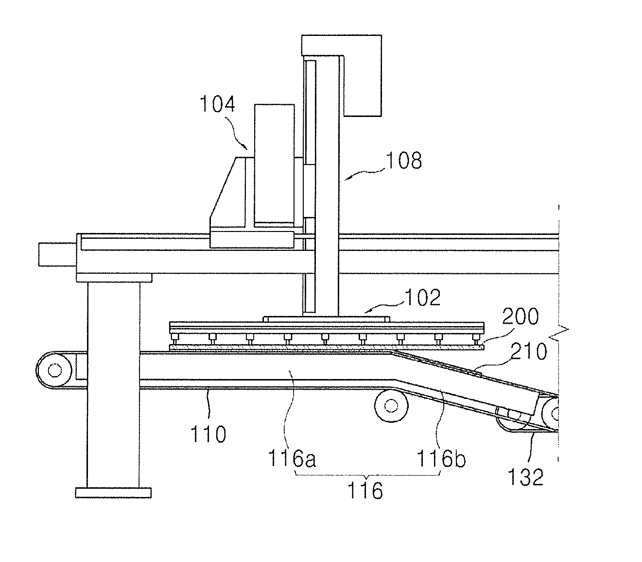
[0009]Embodiments of the present invention present invention provide a carrier substrate removing apparatus capable of improving (e.g., reducing) processing expenses and processing time by rapidly determining the presence of defects in a flexible substrate, a display apparatus manufacturing system, and a method of manufacturing the display apparatus.
[0022]When the transmittance of the separated carrier substrate is less than a reference value, the controller may be configured to control the laser irradiation apparatus to reduce the energy density of the laser.
[0024]The controlling the energy density of the laser may include reducing the energy density of the laser when the transmittance measured by the transmittance measuring unit is less than a reference value.

Problems solved by technology

However, because it is difficult to handle such a flexible substrate because the flexible substrate is so thin, a carrier substrate formed of a glass material and having a relatively greater thickness than the flexible substrate is generally prepared so that the flexible substrate can be attached thereto, and then, processes such as a display unit forming process may be performed.
However, the laser irradiation process may cause defects to occur on the flexible substrate, but the flexible substrate separated from the carrier substrate removing apparatus generally proceeds to post processes (post-processing steps) regardless of whether there are defects, thus unnecessarily consuming processing expenses and time.

Method used


Image

  • Carrier substrate removing apparatus, display apparatus manufacturing system, and method of manufacturing the display apparatus
  • Carrier substrate removing apparatus, display apparatus manufacturing system, and method of manufacturing the display apparatus
  • Carrier substrate removing apparatus, display apparatus manufacturing system, and method of manufacturing the display apparatus

Examples


Embodiment Construction

[0036]The attached drawings for illustrating exemplary embodiments of the present invention are referred to in order to gain a sufficient understanding of the present invention, the merits thereof, and the objectives accomplished by the implementation of the present invention.

[0037]Hereinafter, the present invention will be described in detail by explaining embodiments of the invention with reference to the attached drawings. Like reference numerals in the drawings denote like elements.

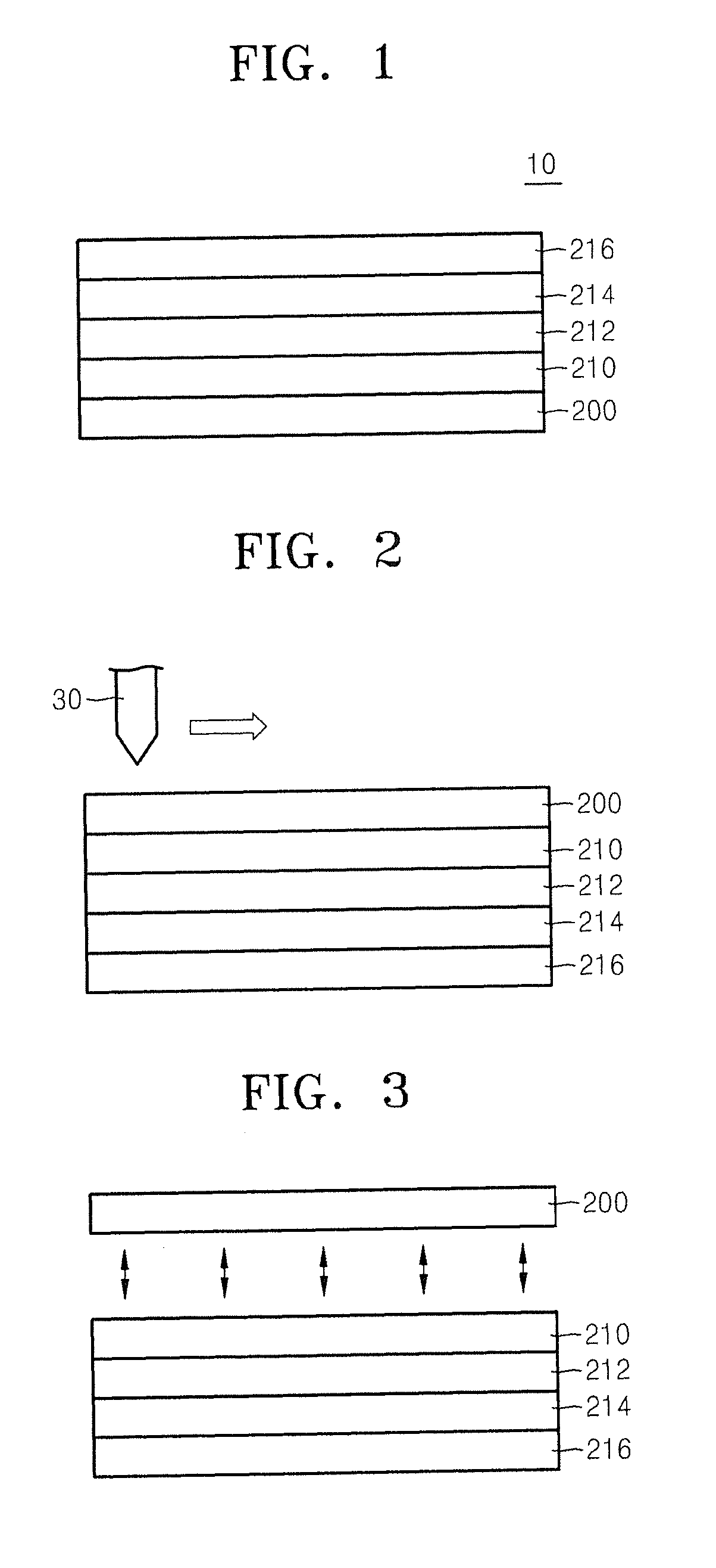
[0038]FIG. 1 is a schematic cross-sectional view of a flexible electronic device 10 using a carrier substrate 200 according to an embodiment of the present invention.

[0039]Referring to FIG. 1, the flexible electronic device 10 includes the carrier substrate 200, a flexible substrate 210, a thin film transistor (TFT) array 212, a display layer 214, and an encapsulation layer 216.

[0040]In other embodiments, the flexible electronic device 10 may further include an adhesion layer filling a space between t...


PUM

PropertyMeasurementUnit
thicknessaaaaaaaaaa
sizeaaaaaaaaaa
transmittance measuringaaaaaaaaaa

Abstract

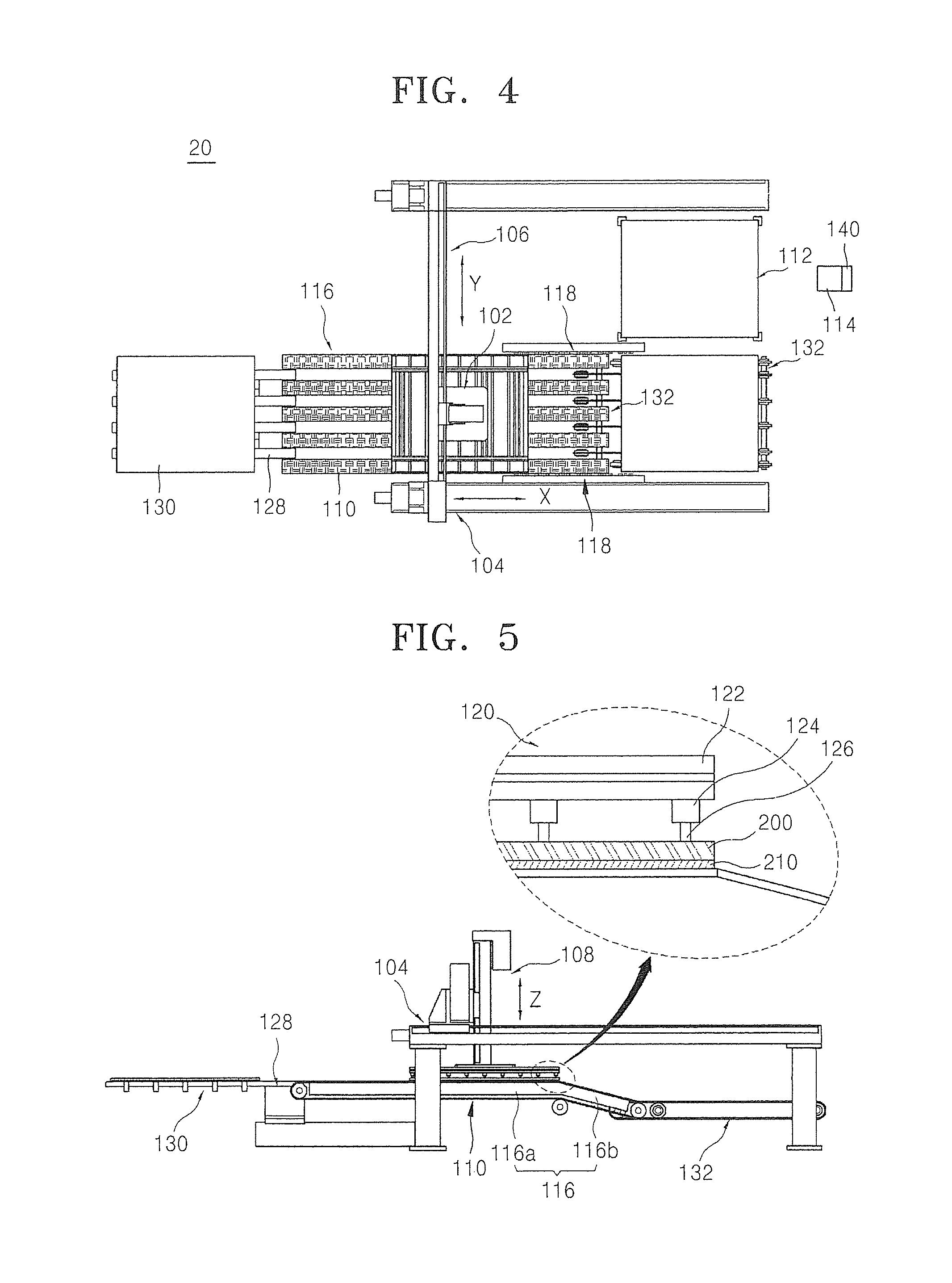
A carrier substrate removing apparatus configured to separate a flexible substrate bonded to a carrier substrate includes a carrier substrate holding unit configured to hold the carrier substrate separated from the flexible substrate; an inclined separation unit configured, with the carrier substrate holding unit, to separate the flexible substrate from the carrier substrate and to transport the flexible substrate at an angle; and a transmittance measuring unit configured to measure a transmittance of the separated carrier substrate.

Description

CROSS-REFERENCE TO RELATED PATENT APPLICATION[0001]This application claims priority to and the benefit of Korean Patent Application No. 10-2012-0130510, filed on Nov. 16, 2012, in the Korean Intellectual Property Office, the disclosure of which is incorporated herein in its entirety by reference.BACKGROUND[0002]1. Field[0003]Embodiments of the present invention relate to a carrier substrate removing apparatus, a display apparatus manufacturing system, and a method of manufacturing a display apparatus.[0004]2. Description of the Related Art[0005]Research is being conducted to develop a display apparatus such as an organic light-emitting display apparatus that is formed to be thin and flexible due to its driving characteristics. Recently, flexible display apparatuses in which a display unit is formed on a flexible substrate having a thickness of about 50 to 100 μm have been highlighted.[0006]However, because it is difficult to handle such a flexible substrate because the flexible subs...

Claims


Application Information

Patent Timeline
Patent Type & Authority Patents(United States)
IPC IPC(8): B32B38/10B32B43/00G02F1/13G02F1/1333H01L51/00H01L51/56
CPCB32B43/006G02F1/1303H01L51/003H01L51/56B32B2457/20G02F1/133305G02F2202/28Y10T156/19Y10T156/1158Y10T156/1917Y10T156/1132Y10T156/1944H10K71/80H10K71/00H05B33/10
Inventor KWEON, JIN-KEONHEO, KYUNG-HOEKIM, KI-TAEK
Owner SAMSUNG DISPLAY CO LTD
Learn More